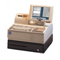
2. Install the D15 base mounting bracket using 4 M3x5
Phillips Flat Head screws.
3. Thread the VF50 cable through the display pole and
install the short display pole using three M5 screws.
Do not tighten screws completely.
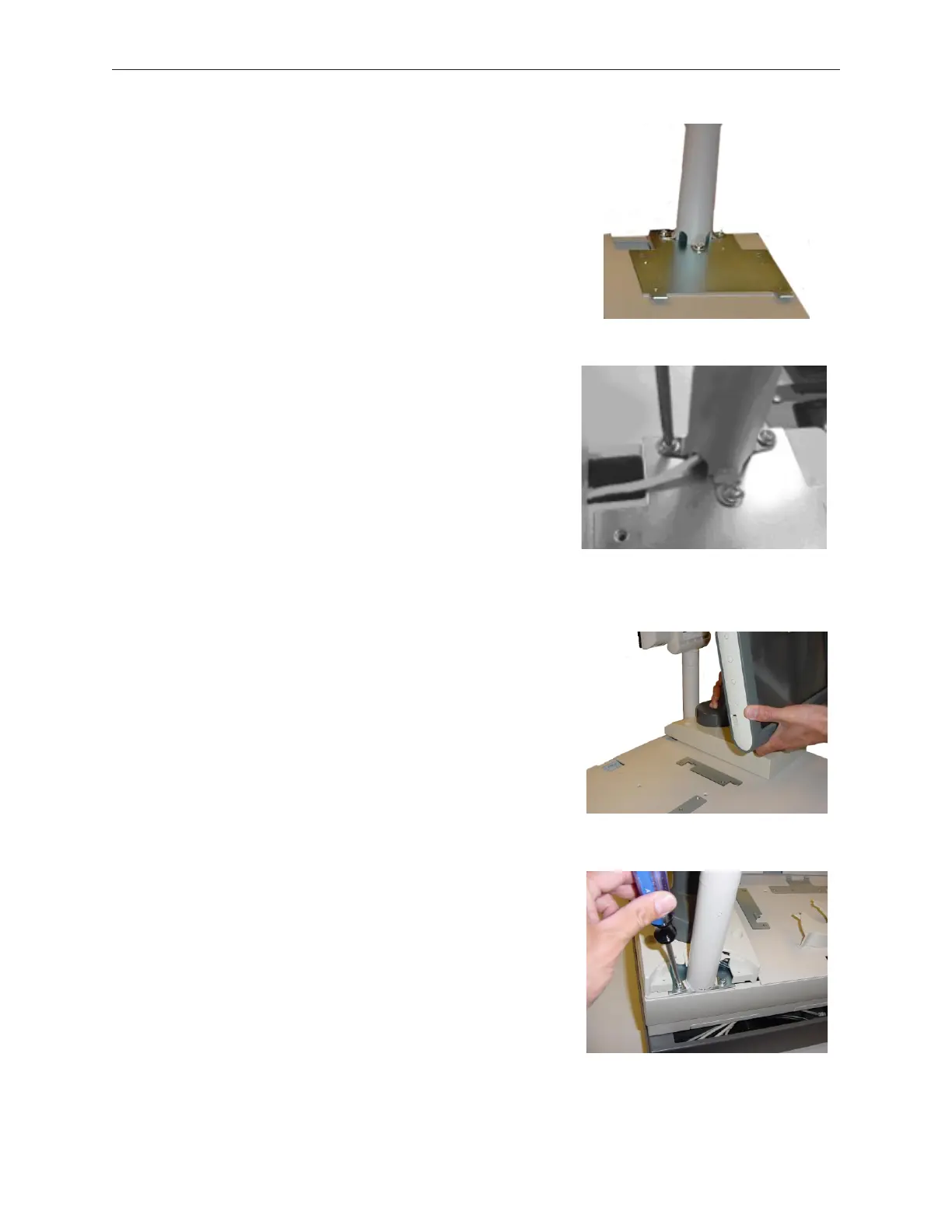
4. Route the PoS end of the display cable as shown.
5. Attach the D15 display assembly (temporarily) to
help center and position the short display pole.
5. Tighten the two rear M5 screws. Remove the D15
display assembly and tighten the third M5 screw.
5-52 Rev 3.0 90000291
TeamPoS 2000 MAINTENANCE MANUAL