hole on the top cover where a bracket will not be used. For dispersed configurations, all
holes are covered.
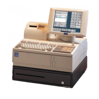
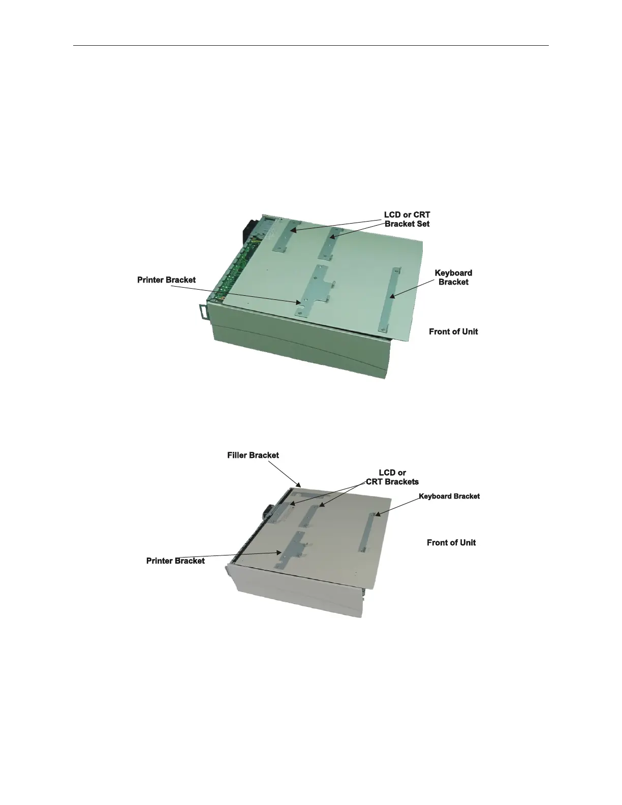
5.1.5.2 D12 and A12 Stacking Bracket Locations
The following shows peripheral bracket locations on the compact and standard control
units. If a D12/A12 LCD and model DT50/DT50II printer are installed on a standard
unit, a filler occupies the remaining space. See next section.
Compact Unit
Standard Unit
5.1.5.3 Filler Unit Installation on a Standard Unit
The filler is used to occupy the free space on a standard control unit with a stacked LCD
(either 12.1" or 15") and model DT50/DT50II printer. An optional connector cover (not
5-8 Rev 3.0 90000291
TeamPoS 2000 MAINTENANCE MANUAL