4-23
Chapter 4 Connection to the External Devices Setup for the External Device Connection
When the DS-8007 is used
The setting items are different for the DS-8007 and HS-8000.
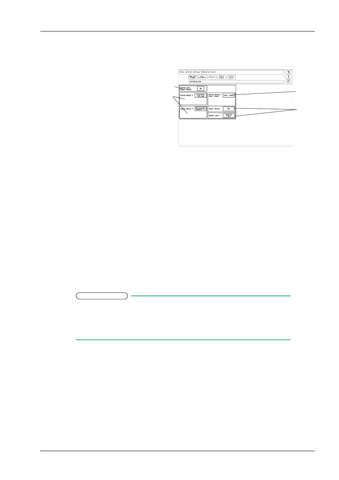
1When the DS-8007 is used, the screen shown
on right will be displayed.
2Set the "Analog Synchronized Signal Output".
Select from [ON]/[OFF].
3Set the "Analog Output 1", "Analog Output 2".
Select from [Selected ECG Lead]/
[Displayed ECG Lead]/[Multiparameter
Connector 1-1]/[Multiparameter Connector
1-2]/[Multiparameter Connector 2-1]/
[Multiparameter Connector 2-2].
When [Selected ECG Lead] is selected, press the key for "Output Lead Sel.".
Select from [I]/[II]/[III]/[aVR]/[aVL]/[aVF]/[V1] to [V6].
4Set the "Analog Output 3".
Select from [Selected ECG Lead]/[Displayed ECG Lead]/[Multiparameter Connector 1-1]/[Multiparameter
Connector 1-2]/[Multiparameter Connector 2-1]/[Multiparameter Connector 2-2]/[Sync. Signal].
5When [Sync. Signal] is selected, select also the output signal.
1 Press the key for "Signal Output", and select from [HR]/[RR].
[HR]: Synchronized signal based on HR source (ECG) will be output.
[RR]: Synchronized signal based on RR source (impedance) will be output.
2 Set the "Output Logic".
[Positive Logic]: Positive synchronized signal will be output.
[Negative Logic]: Negative synchronized signal will be output.
The QRS synchronized signal is a delay output (35 msec or less during Monitor/
Diagnosis Mode).
The delay time varies depending on the filter mode setting and input waveform type.
When the QRS synchronized signal is input to the external device, make sure that the
delay time is within the acceptable range of the connected device.