6-38
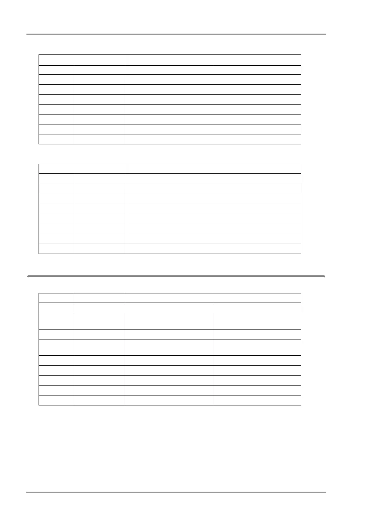
Chapter 6 Setup Item/Default Value External Connection (Pin Assignments)
COM4 Connector (Alarm External Input)
COM5 Connector (Reserved)
Status I/O Signal (Status II Connector)
*:If isolation is necessary for RS-232C and status connector, use alarm input 2 and output 2.
No. Signal Type Note Signal Level
1 RESET Port Reset
2 EXT_IN+(Logic) Alarm External Input+
3 TxD Serial Transmission Data Output RS232C
4 GND_ISO Isolation Ground
5 RxD Serial Reception Data Input RS232C
6 +5V +5V Power +5V Power Supply (150mA)
7 EXT_IN-(Return) Alarm External Input Return
8 NC Not connected
No. Signal Type Note Signal Level
1 COM_RST Reset Output Open Collector Output
2 NC Not connected
3 TxD Serial Transmit Data Output RS232C
4GND GND
5 RxD Serial Reception Data Input RS232C
6 +5V +5V Power +5V power supply (150mA)
7 NC Not connected
8 NC Not connected
No. Signal Type Note Signal Level
1 ALARM_OUT1 Alarm Output1 Logic TTL
2
ALARM_OUT2+ Alarm Output2+ (Isolation)
Photo MOS
Relay Contact
3 TxD Serial Transmission Data Output RS232C
*
4
RxD/ALARM1
Serial Reception Data Input/ALARM1
Input
RS232C
*
/ Logic
5 ALARM2_IN+ Alarm Input 2 (Isolation) Logic Input
6 ALARM2_IN- Alarm Input 2 Return (Isolation)
7 +5V +5V Power Supply Input +5V Power Supply (150mA)
8 ALARM_OUT2- Alarm Output2- (Isolation) Photo MOS Relay Contact
9 GND_ISO Isolation Ground


 To Next Page