4-21
Chapter 4 Connection to the External Devices Setup for the External Device Connection
Status Output Setup
The alarm can be output from the status input/output connector or I/O connector (optional) on the Main Unit (DSC-
8500 Series).
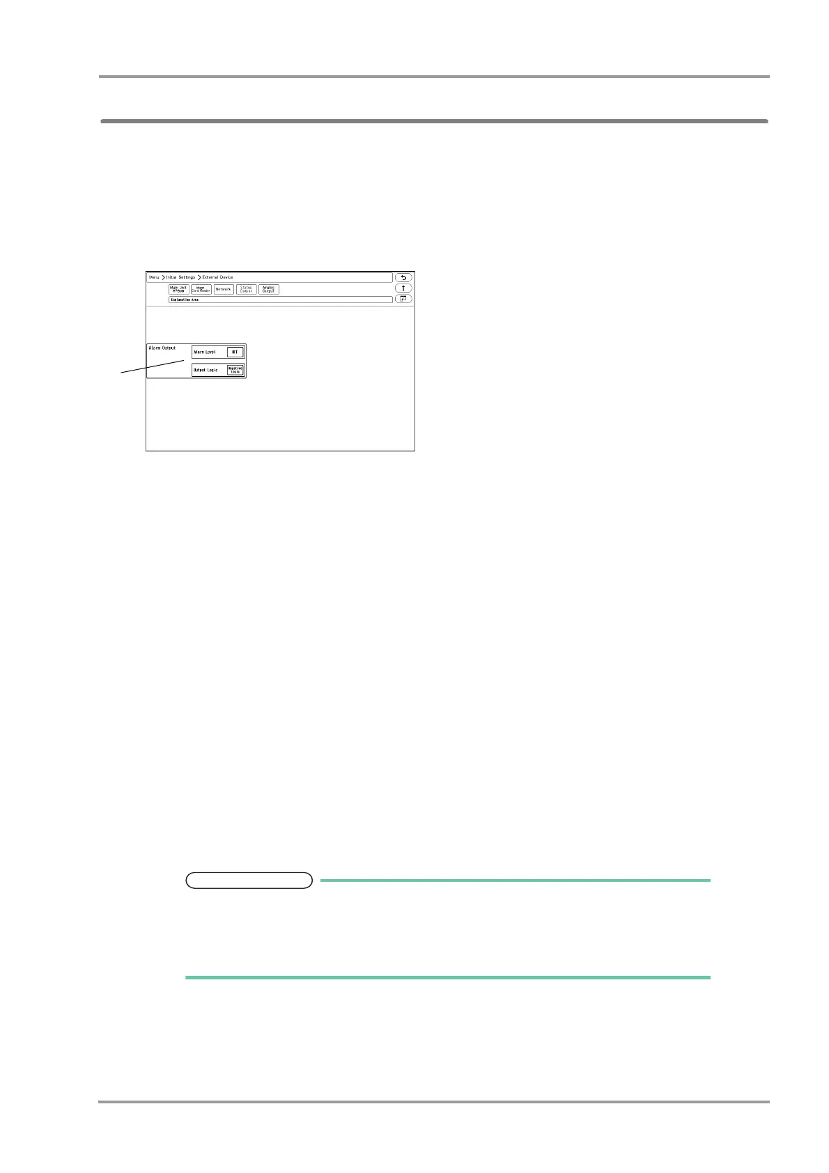
1Press the [Menu], [Initial Settings], [External Device], [Status Output] keys.
The "Status Output" setup menu will be displayed.
2Select the alarm to output.
1 Press the key for "Alarm Output".
The dropdown list will be displayed.
2 Select from [OFF], [APNEA], [Level H] / [Level H,M] / [Level H,M,L].
[Level H]: Level H alarm will be output.
[Level H,M]: Level H, M alarm will be output.
[Level H,M,L]: Level H, M, L alarm will be output.
[APNEA]: Apnea alarm will be output.
[OFF]: Alarm will not be output.
3 Press the key for "Output Logic".
The dropdown list will be displayed.
4 Select from [Positive Logic]/[Negative Logic]/[Pulse].
[Positive Logic]: Positive synchronized signal will be output.
[Negative Logic]: Negative synchronized signal will be output.
[Pulse]: A square wave of 440 ms cycle will be output.
Refer to "Status I/O Signal (Status II Connector)" P6-38 for connector pin assignments
of the alarm output.
The equipment status alarm will be output as level L.To output the equipment status
alarm, select [Level H,M,L].