hold the tube in place. Insert a 2 mm hex key through the larger hole to partially back out the screw that
fastens the conical cap to the plastic tube. Pull the cap out of the rail. Pull out the key in the tube hole and
let the tube drop down in the upright.
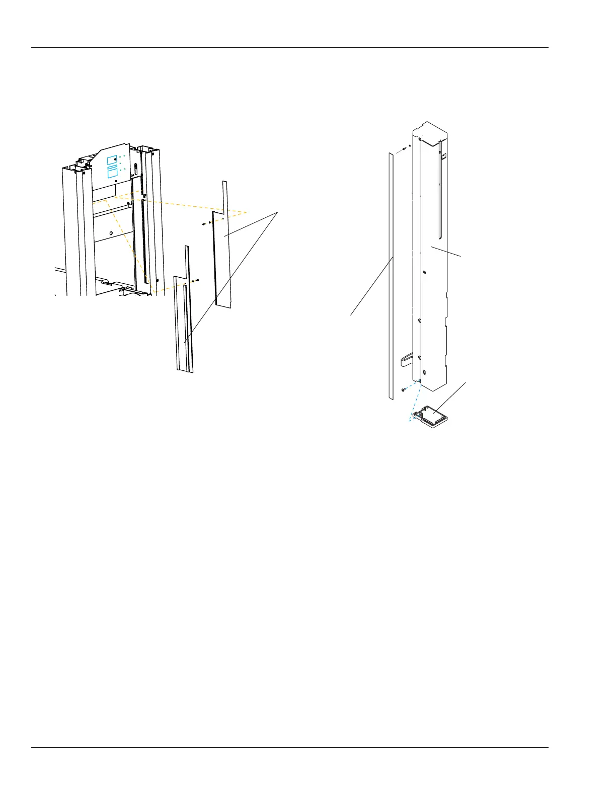
Decorative strip
Upright
Bottom endcap
Wire covers
Figure 5-25 Upright Decorative Strips, End Caps, and Wire Covers
7. Remove the two at head screws (3mm hex key) that hold the canopy bracket to the lift rail.
8. Use a 2.5 mm hex key to loosen the 2 screws in the keyhole slots and remove the 6 remaining screws that
secure the controller cover, then remove the cover.
9. Slide the decorative strip up about ½” in the groove on the outside of the upright to access hardware
that secures the lower end cap. You may wish to use a piece of tape to grip the strip. Use a 2.5 mm hex
key to remove the screw, then remove the cap. (On units equipped with the Servo Oxygen option, refer
to the “5.14.5 Endcap Safety Valve” section for instructions on removing the endcap manifold.) Slide
the decorative strip down to access the screw that secures the upper end cap and remove the screw,
countersunk washer, and decorative strip. The upper end cap can now be removed by lifting the center
cap up out of the lift rail, pushing the exhaust door back, then sliding the outside end cap up and past the
spring.
92 6600-0343-000 104 © 2001 by Datex-Ohmeda, Inc.. All rights reserved.
Chapter 5: Repair Procedures

 Loading...


