Intervention Display Driver bd J21 pins 1-8 Closed when switch is pressed
Manual Mode Inc. Display Driver bd J21 pins 1-9 Closed when switch is pressed
Canopy hand control
Left up Relay bd J35 pins 2-4 Closed when switch is pressed
Left down Relay bd J35 pins 3-4 Closed when switch is pressed
Right up Relay bd J35 pins 6-5 Closed when switch is pressed
Right down Relay bd J35 pins 7-5 Closed when switch is pressed
4.6.6 Humidier Heater/Safety Thermostat
The humidier has two separate heater elements rated at 225 watts at 104 volts. They are connected in
parallel for 115 volt operation and in series for 230 volt operation. The humidier safety thermostat is in series
with the heater. It opens at 130 +/-5 C and closes at 90 +/-8 C. Measure the resistance at J53.2 to J53.3.
The resistance of each heater is about 144 ohms so it should measure about 72 ohms for 115 units, 288 ohms
for 230 units.
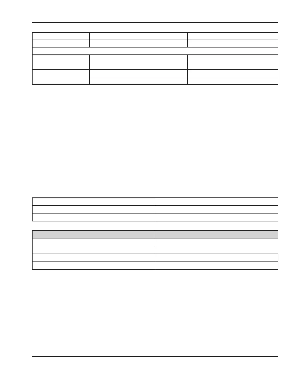
4.6.7 Compartment Air Probe and Patient Probes
Use the service screen to read the temperature of the compartment and patient probes.
There are two thermistors in each air probe or patient probe. During stable temperature conditions the
thermistors should read the same resistance within a few ohms.
Patient probe #1 Control bd J4 pins 1-3, 2-3
Patient probe #2 Control bd J2 pins 1-3, 2-3
Compartment Air probe Control bd J1 pins 1-2, 3-4
Temperature (C) Resistance (Ohms)
20 12527
25 10000
30 8037
35 6500
© 2001 by Datex-Ohmeda, Inc.. All rights reserved. 6600-0343-000 104 61
Chapter 4: Troubleshooting

 Loading...


