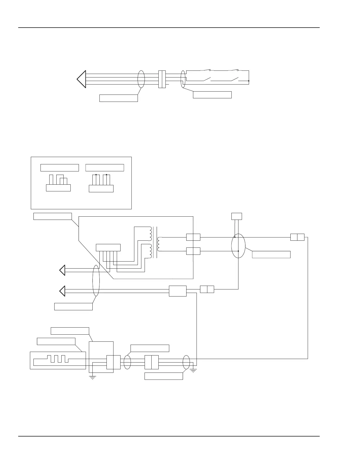
Figure 6-50 Wiring Diagram: Radiant Heater Relay Board 9 or Lower
Solid State Relay
+
- AC
AC
1
1
2
3
4
1
1
2
3
4
5
6
1
2
3
HTR DOOR OPEN
1
2
1
2
3
4
230V
1
2
3
4
5
6
HTR DOOR OPEN
115V
1
2
3
4
5
6
HTR DOOR CLOSED
1
1
HTR DOOR CLOSED
1
1
1
2
3
1
2
3
1
3
4
2
5
6
1
2
3
1
1 2
1
GND
brown
Relay Board
6600-0752-700
brown
shield
HTRDOORNO
Isolation Transformer
green
Heater Door
Sensors
Yellow
red
black
HTRDOORNC
6600-0220-850
6600-0867-700
black
black
red
brown
Black
6600-0710-700
Relay Board
6600-0815-700
black
To J38 on
Configuration Plug Group 1
Brown
Orange
6600-0748-702
Configuration Plug
Group 1
black
orange
Blue
White
black
6600-0748-701
Htr sigblack
(Shown with heater door in closed position)
6600-0882-700
shield
6600-0816-700
brown
green
+12V
yellow
Heater
Neutral
6600-1003-600
To J49 on
Phase
6600-0710-700
Relay Board
red
SHIELD
blue
red
To J31 on
blue
green/yellow
6600-1535-700
See Incubator Section of
Wiring Diagram.
To Incubator Heater Harness
part number 6600-0709-700
228 6600-0343-000 104 © 2001 by Datex-Ohmeda, Inc.. All rights reserved.
Chapter 6: Illustrated Parts

 Loading...


