4. To remove the LED board, disconnect the electrical connectors, then remove the 2 standos (6mm wrench)
that hold the board in place, and then the 2 nuts with hardware.
5. To remove the EL display, disconnect the electrical connectors, then remove the 2 nuts that hold the display
in place. Be careful not to get nger prints on the display and be sure it is clean before replacing it.
6. The standos that hold the back cover also secure the bezel to the front of the display cage. Remove the
standos (6mm wrench) and remove the bezel. To replace the membrane switch panel, rst disconnect its
electrical connector and then peel it o the display cage. Be careful to remove all residue adhesive from the
module before installing a new membrane panel. The membrane panel can not be repositioned once it has
been applied without damaging it.
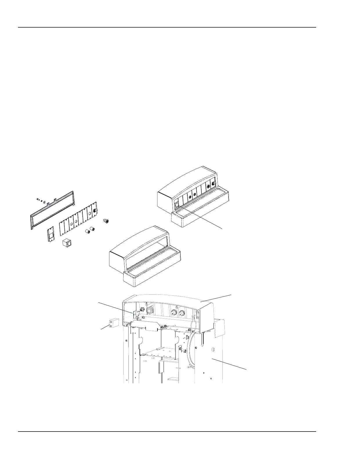
5.13.2 Probe Panel
Refer to “Figure 5-58 Probe Panel” and “Figure 6-1 Probe Panel Assembly”.
Power switch
Figure 5-58 Probe Panel
Battery holder
Battery
Probe panel housing
Electrical enclosure
138 6600-0343-000 104 © 2001 by Datex-Ohmeda, Inc.. All rights reserved.
Chapter 5: Repair Procedures
 Loading...


