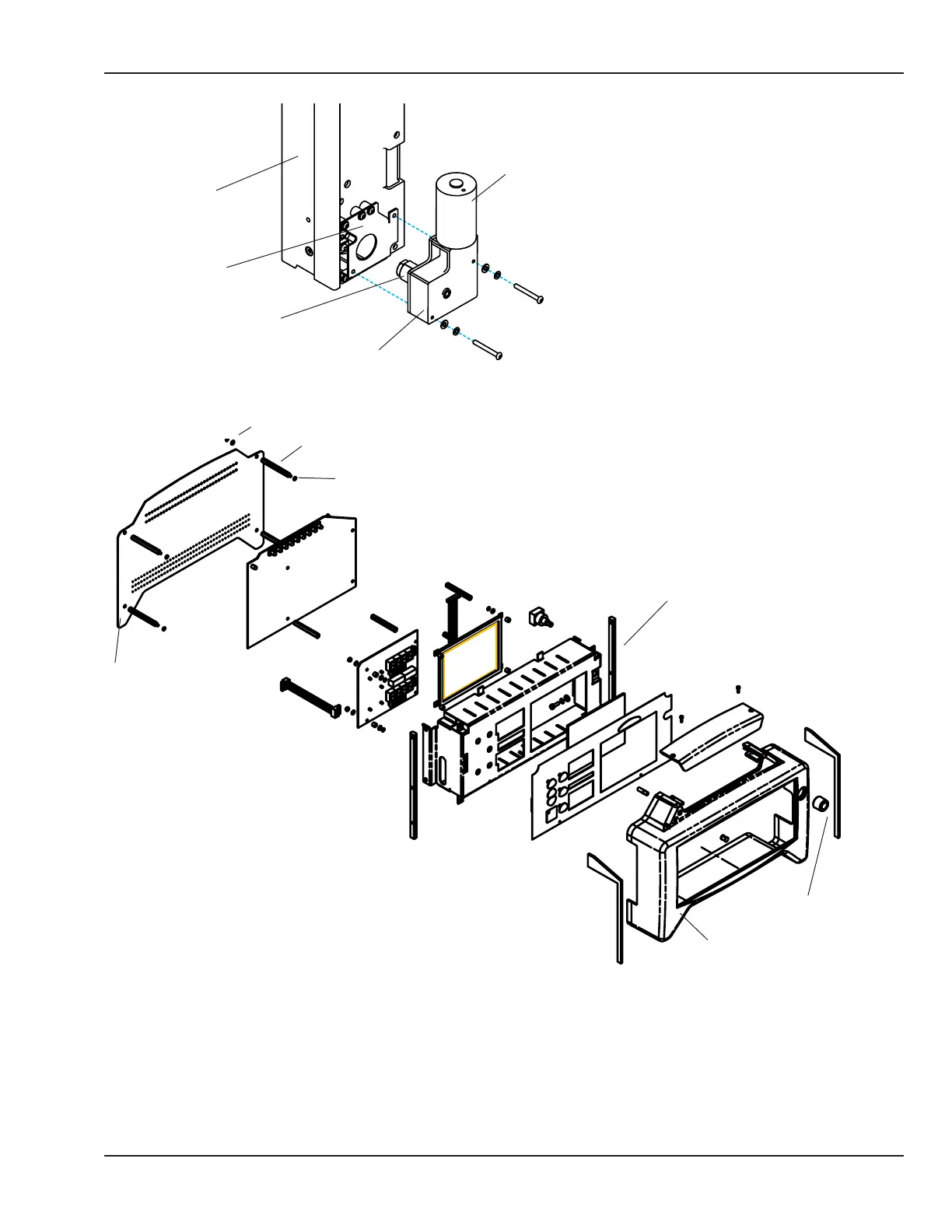
Lift Motor
Gear box
Lift Motor Coupler
Motor bracket
Right upright
Figure 5-26 Removing the Lift Motor
NOTE: Illustration expanded
for clarity.
Back cover
Stando
Lock washer
Nut bar
Control knob
Font bezel
Figure 5-27 Display Module Disassembly
10. Using a 2mm hex key, remove the 4 button head socket screws and lock washers that secure the back
cover to the display module and remove the panel.
11. Remove the control knob from the front of the display by pulling it straight o its shaft.
© 2001 by Datex-Ohmeda, Inc.. All rights reserved. 6600-0343-000 104 93
Chapter 5: Repair Procedures

 Loading...


