17. Dress the wire harnesses and install a cable tie.
18. Slide the reservoir seal into place.
19. When installing the humidier assembly, rotate the cylinder so the max line is visible.
5.13 Controller and Display Module Procedures
5.13.1 Display Module
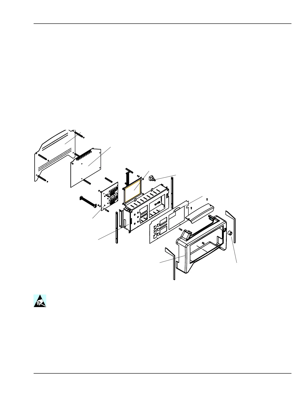
Refer to “Figure 5-57 Display Module”.
Back cover
Display driver board
LED board
EL display
Rotary encoder
Membrane switch panel
Display bezel
Control knob
Display cage
Figure 5-57 Display Module
1. Remove the 4 screws that hold the back cover on the display module and remove the cover.
2. To remove the display driver board, rst remove the 4 screws the hold the board to the standos, then
disconnect the electrical connectors.
3. To replace the rotary encoder for the EL display, pull the control knob o the shaft, disconnect the electrical
connector, remove the nut that secures the encoder, and remove the encoder.
© 2001 by Datex-Ohmeda, Inc.. All rights reserved. 6600-0343-000 104 137
Chapter 5: Repair Procedures

 Loading...


