4. Install a new vent screen and reinstall the vent cover.
5. Perform the Pre-use Checkout.
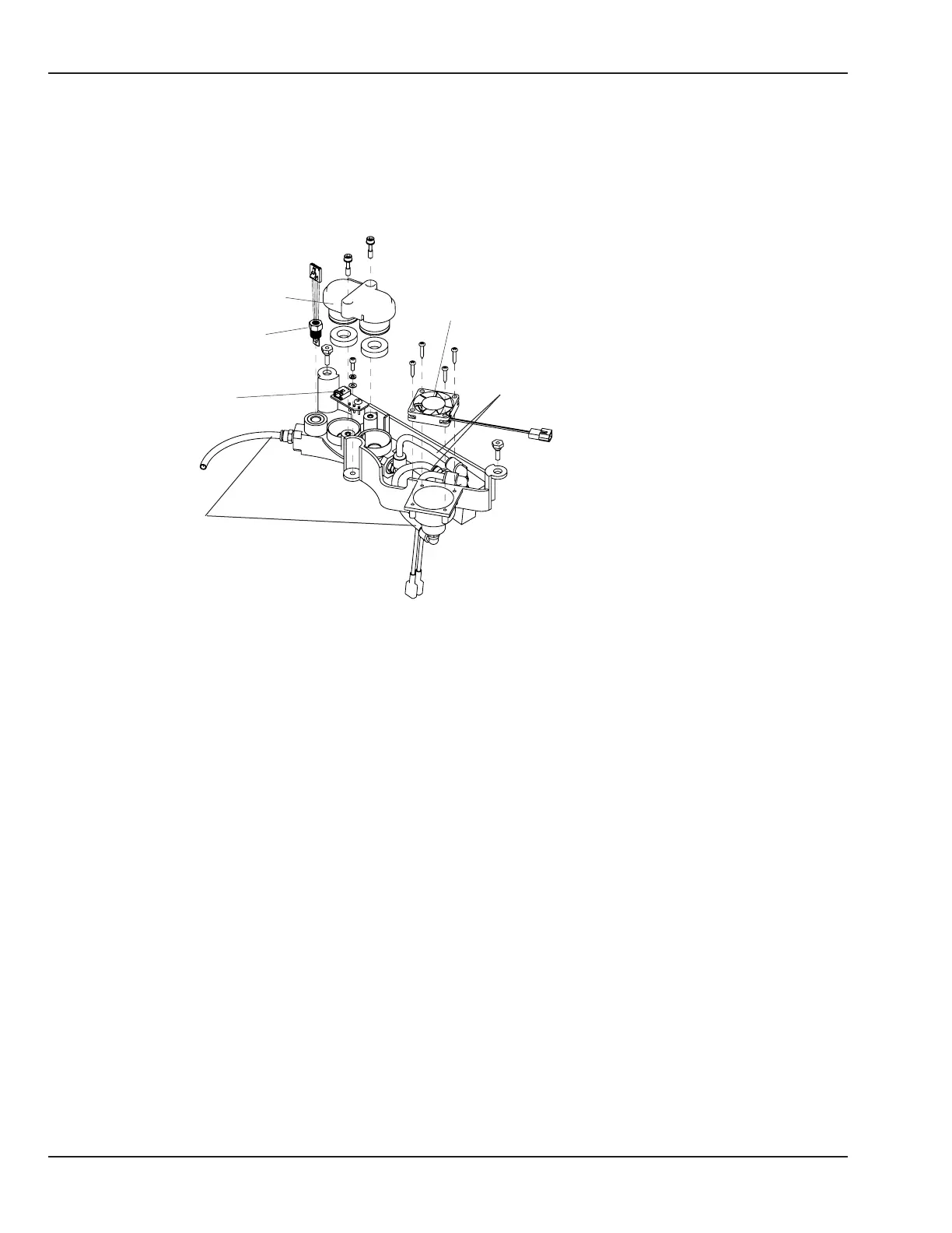
5.14.3 Sensor Housing Repairs
Sensor housing cover
Calibration fan
PC board
Sensor plug assembly
White hoses
Black hoses
Figure 5-61 Sensor Housing
5.14.3.1 Sensor Housing Repairs: Boards, Calibration Fan Assembly, and Sensor Plug Assembly
1. Slide the drawer to one side and using a 3mm hex key, loosen the captive screws in the chassis cover
sensor housing door and swing the door down to access the sensor housing.
2. Using a 3mm hex key, loosen the two M4 socket head screws that secure the sensor housing cover, and
remove the cover.
3. To replace the half of the PC board inside the sensor housing cover, use 2.5 mm hex key to remove the 2 M4
button head screws that secure it to the cover.
4. To replace the half of the PC board inside the sensor housing, disconnect from the wire harness and
remove the single M4 button head screw that holds it to the housing. Perform the Pre-use Checkout
5. To replace the calibration fan, disconnect its electrical connector and remove the 4 self tapping screws
that secure it to the sensor housing. Install replacement fan so ow arrow on side points up into chassis.
Perform the Pre-use Checkout
144 6600-0343-000 104 © 2001 by Datex-Ohmeda, Inc.. All rights reserved.
Chapter 5: Repair Procedures

 Loading...


