4.4.23 System Failure 27
System failure 27 indicates: Defective non-volatile memory.
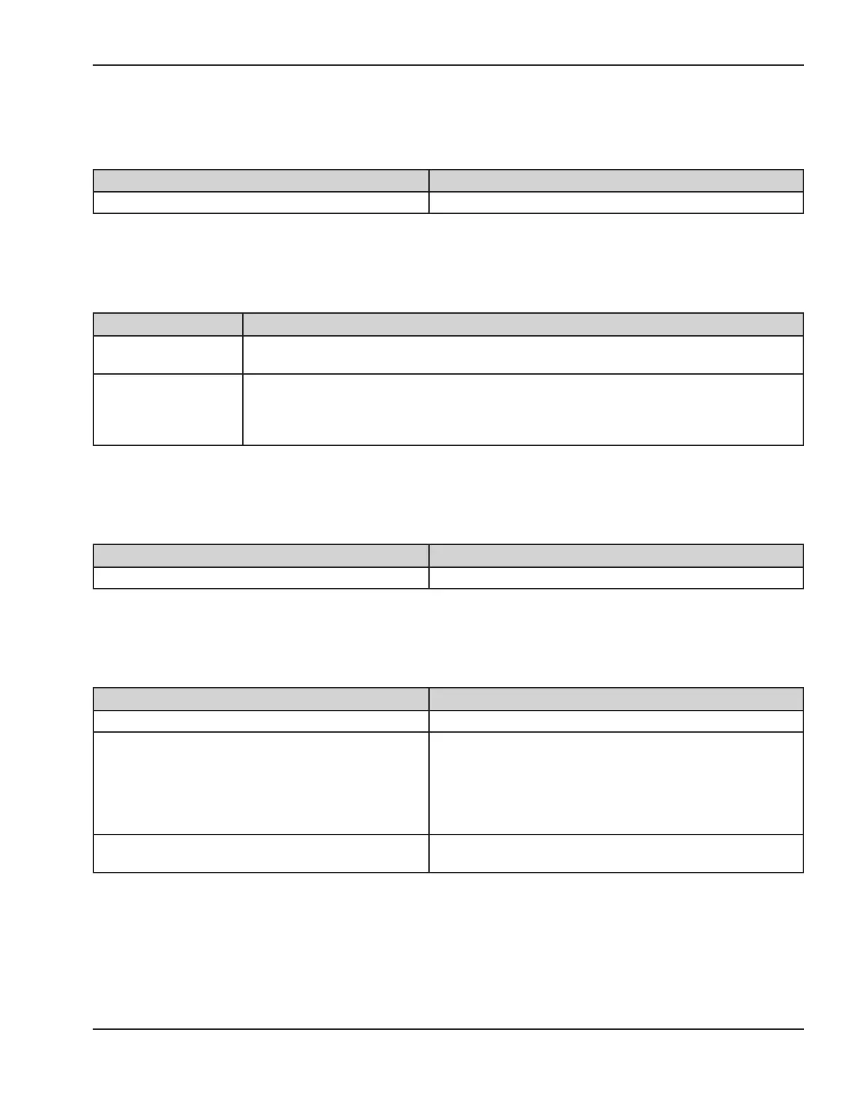
Cause(s) Action(s)
Defective circuit on control board. Replace the control board.
4.4.24 System Failure 28
System failure 28 indicates: During operation, the display driver board lost communication with control board.
Cause(s) Action(s)
Refer to system failure
0.
Power down the unit, during the self-test the unit should detect system failure 0. Follow the
instructions for system failure 0.
Defective at ribbon
cable between control
board and display
board.
If system failure 28 persists without system failure 0, replace the at ribbon cable between
control board and display board.
4.4.25 System Failure 29
System failure 29 indicates: Defective signal on control board.
Cause(s) Action(s)
Defective control board Replace the control board.
4.4.26 System Failure 30
System failure 30 indicates: Mains voltage reading LV1 is outside of the expected range.
Cause(s) Action(s)
Mains Voltage Comp Circuit is not calibrated correctly. Calibrate the line voltage.
High or low mains voltage. This failure is triggered if the
mains voltage is outside the following ranges:
• 100V: 80-115V
• 115V: 95-132V
• 230V: 195-270V
Connect to proper mains voltage source
Defective 50 pin ribbon cable between the relay and
control board.
Check for continuity on pin 48 and 49 (LineComp1,2) If
defective replace cable.
© 2001 by Datex-Ohmeda, Inc.. All rights reserved. 6600-0343-000 104 51
Chapter 4: Troubleshooting

 Loading...


