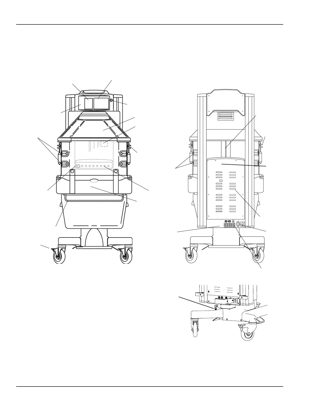
2.8 Cable Connections and Mechanical Controls
Figure 2-1 Connections and Controls
Numeric Temperature Displays
Temperature
Regulation
Controls
Graphics Screen
Tubing Grommets
Standby
Power
Switch
(I/O)
Drainage
Hanger
Caster
Brake
FRONT
Control Knob
Canopy
Probe Jacks
Humidier Reservoir
(air intake lter located
behind reservoir)
Accessory
Power Outlets
Ventilator
Slot
Mains Power
Switch
RS 232
Connector
Tubing Grommets
Side Door
Latch
BACK
Controller
Cover
Side Door Latch
Compartment Probes
Power
Cord
Inlet
Plug retaining brackets
not shown for clarity
O2 connection for
Servo Controlled Oxygen option
18 6600-0343-000 104 © 2001 by Datex-Ohmeda, Inc.. All rights reserved.
Chapter 2: Service Checkout

 Loading...


