GDS-2000E Series User Manual
128
00(NUL), OA(LF), OD(CR), 20(SP),
FF
I
2
C Serial Bus Interface
The I
2
C bus is a 2 wire interface with a serial data line (SDA) and
serial clock line (SCLK). The I
2
C protocol supports 7 or 10 bit
addressing and multiple masters. The scope will trigger on any of
the following conditions: a start/stop condition, a restart, a missing
acknowledge message, Address, Data or Address&Data frames.
The I
2
C trigger can be configured for 7 or 10 bit addressing with the
option to ignore the R/W bit as well as triggering on a data value
or a specific address and direction (read or write or both).
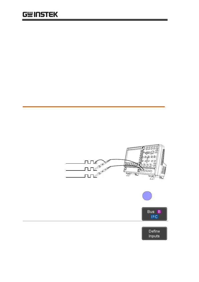
1. Connect each of the bus signals (SCLK, SDA) to
one of the oscilloscope channels. Connect the
ground potential to one of the probes’ ground
clip.
3. Press Bus from the bottom menu
and choose I
2
C from the side menu.
4. Press Define Inputs from the bottom
menu.
5. From the side menu choose the
SCLK input and the SDA Input.
 Loading...


