CONFIGURATION
155
Using Advanced Delay Trigger
1. Set the edge trigger source. This
will set the initializing trigger for
the delay source.
2. Press the trigger Menu key.
3. Press Type from the lower bezel
menu.
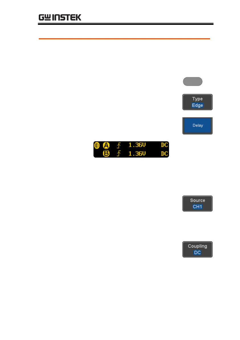
4. Select Delay from the side menu.
The delay trigger indicator appears
at the bottom of the display.
From left: Delay trigger indicator (D),
edge trigger (A), edge slope, edge level, edge
coupling, delay trigger (B), delay slope, delay
trigger level, delay coupling.
5. To set the delay source, press
Source and select a source from the
side menu.
CH1 ~ CH4, AC Line, EXT*
*2 channel models only.
6. Press Coupling from the bottom
bezel menu to select the trigger
coupling or frequency filter
settings.
Choose the coupling from the side menu.
DC, AC, HF Reject, LF Reject
 Loading...


