GDS-2000E Series User Manual
164
Using the Bus Trigger
The Bus trigger is used to trigger and decode
UART, I2C, SPI, CAN and LIN serial bus signals.
UART BUS Trigger Settings
The UART bus trigger conditions can be set at any time after the
bus settings have been set to UART.
1. Set the Bus to UART in the bus
menu.
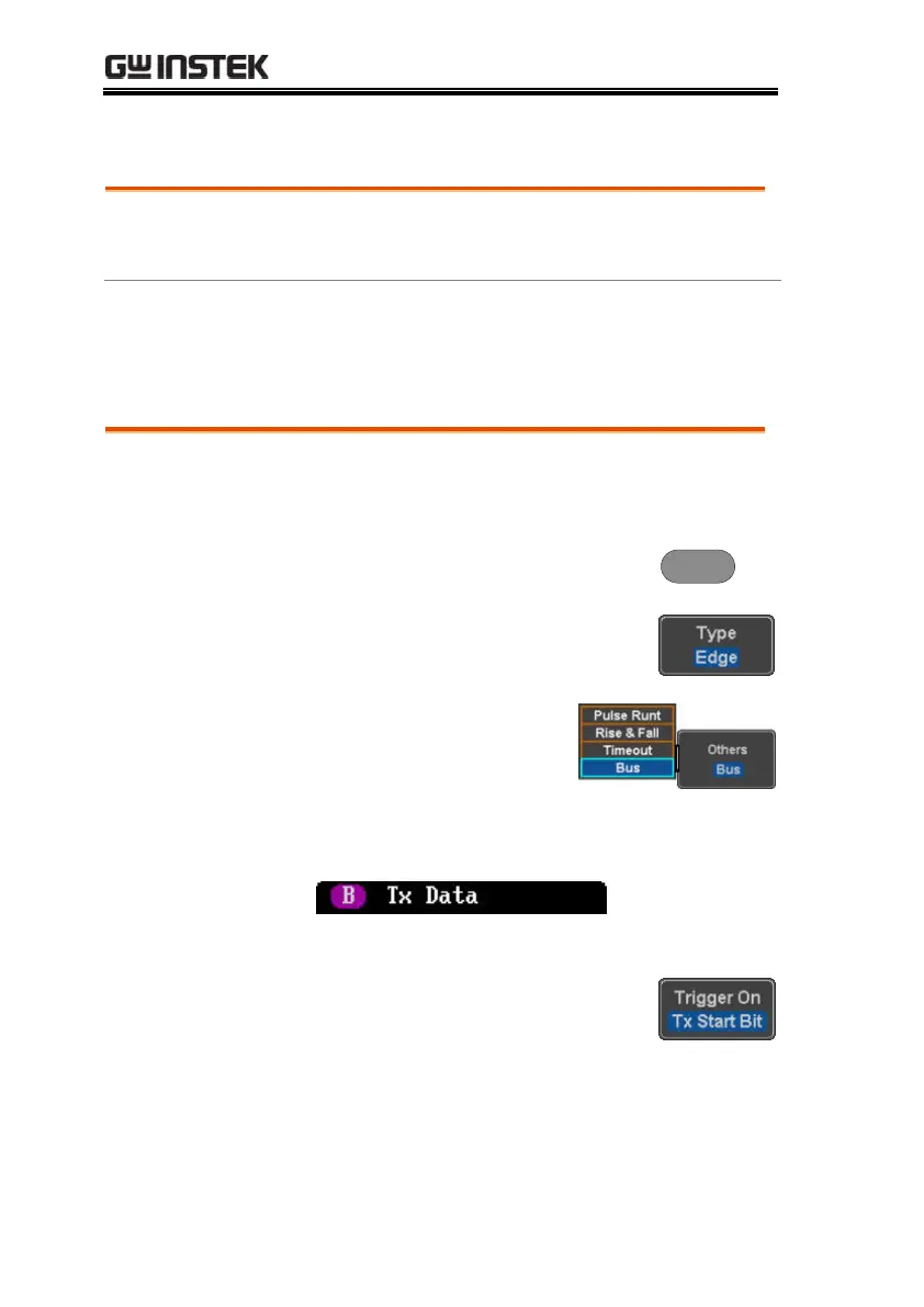
2. Press the Trigger Menu key.
3. Press Type from the bottom menu.
4. Press Others from the side
menu and select Bus.
The Trigger on settings will be reflected on the
Trigger Configuration icon.
From left: Bus trigger, Trigger source
5. Press Trigger On and select the
triggering condition for the UART
bus.
Tx Start Bit, Rx Start Bit, Tx End of
Packet, Rx End of Packet, Tx Data,
Rx Data, Tx Parity Error, Rx Parity
Error
 Loading...


