CONFIGURATION
131
CAN Serial Bus Interface
The controller area network (CAN) bus is a half duplex 2 wire
synchronous serial interface. The CAN bus is a multi-master
communication system that relies on arbitration to solve contention
issues. The GDS-2000E supports both CAN 2.0A and 2.0B. The
CAN bus uses two wires, CAN-High and CAN-Low. These wires
are voltage inverted, and as such, the GDS-2000E only needs one
wire, CAN-High or CAN-Low for decoding.
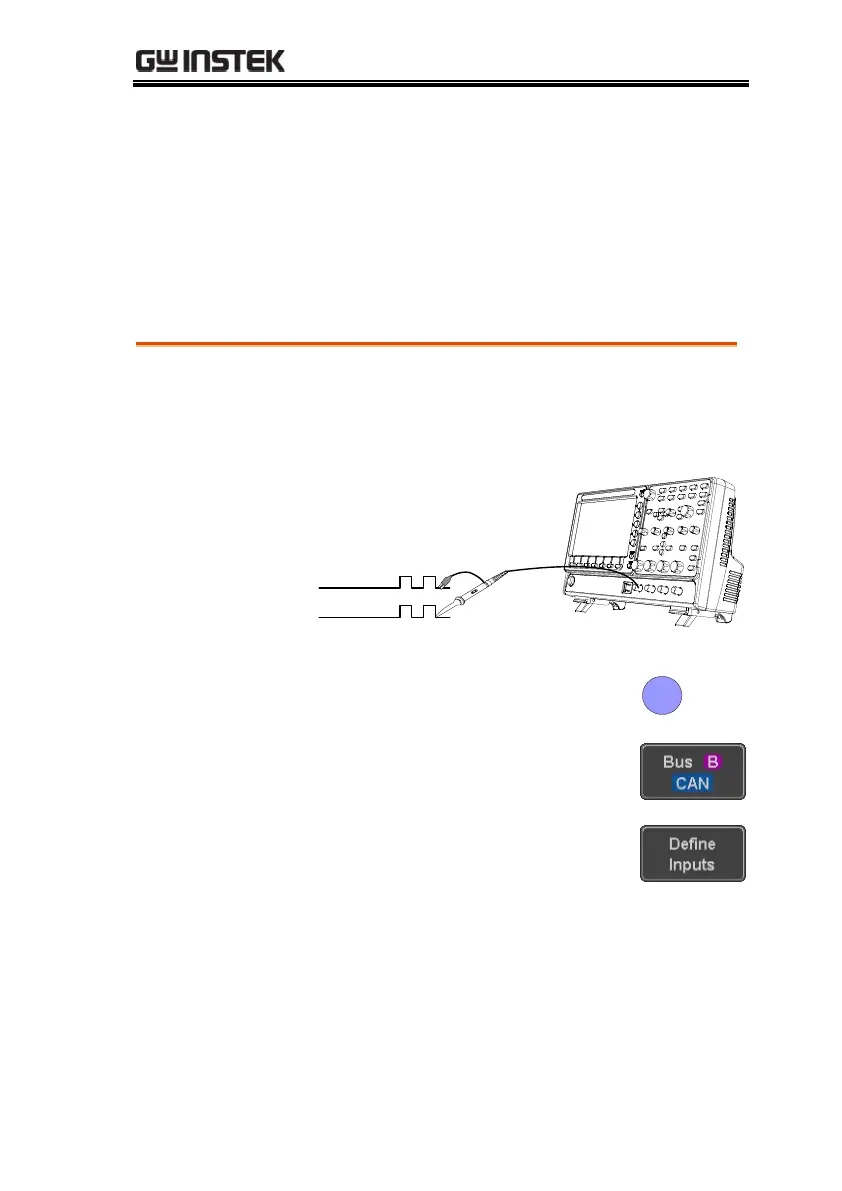
1. Connect the bus signal (CAN Input) to one of
the channel inputs. Connect the ground
potential of the bus to the probe’s ground clip.
3. Press Bus from the bottom menu
and choose the CAN serial bus.
4. Press Define Inputs from the lower
menu.
5. From the side menu choose the
CAN Input inputs and the signal
type.
 Loading...


