CONFIGURATION
171
CAN Bus Trigger
The CAN bus trigger conditions can be set at any time after the bus
setting has been set to CAN.
1. Set the Bus to CAN in the bus
menu.
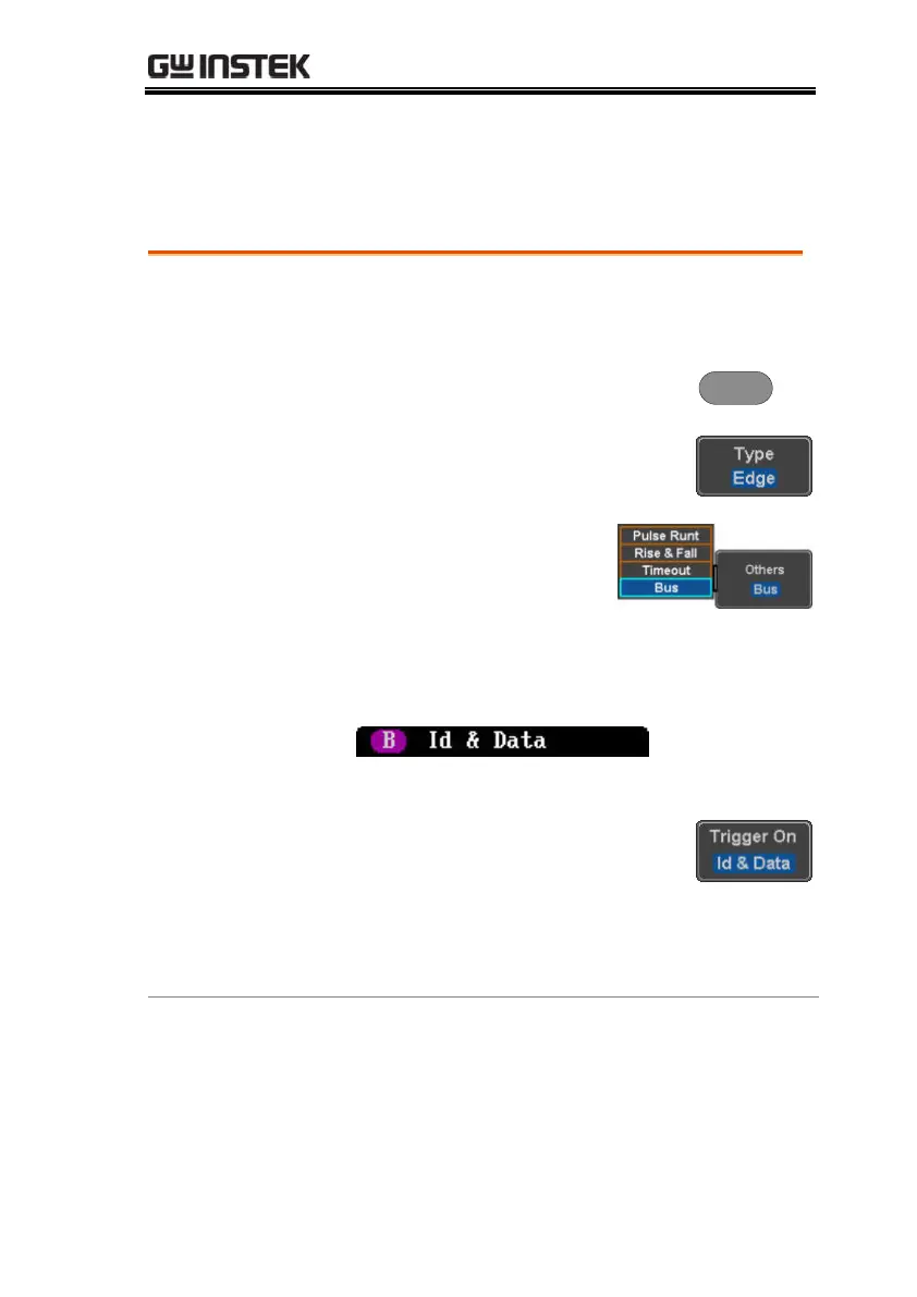
2. Press the Trigger Menu key.
3. Press Type from the bottom menu.
4. Select Others → Bus from
the side menu. The Bus
indicator appears at the
bottom of the display.
The Trigger on settings will be reflected on the
Trigger Configuration icon.
From left: Bus trigger, Trigger source
5. Press Trigger On and select the
triggering condition for the
selected bus.
Start of Frame, Type of Frame,
Identifier, Data, Id & Data, End of
Frame, Missing Ack, Bit Stuffing Err
Trigger On –Type
of Frame
6. If Type of Frame was configured for the Trigger
On setting, then the type of frame can be
configured from the side menu.
Data Frame, Remote Frame, Error
Frame, Overload Frame
 Loading...


