118
6. Remove the security bezel, if any. For more information, see "Replacing the security bezel."
7. Disconnect the cable from the optical drive.
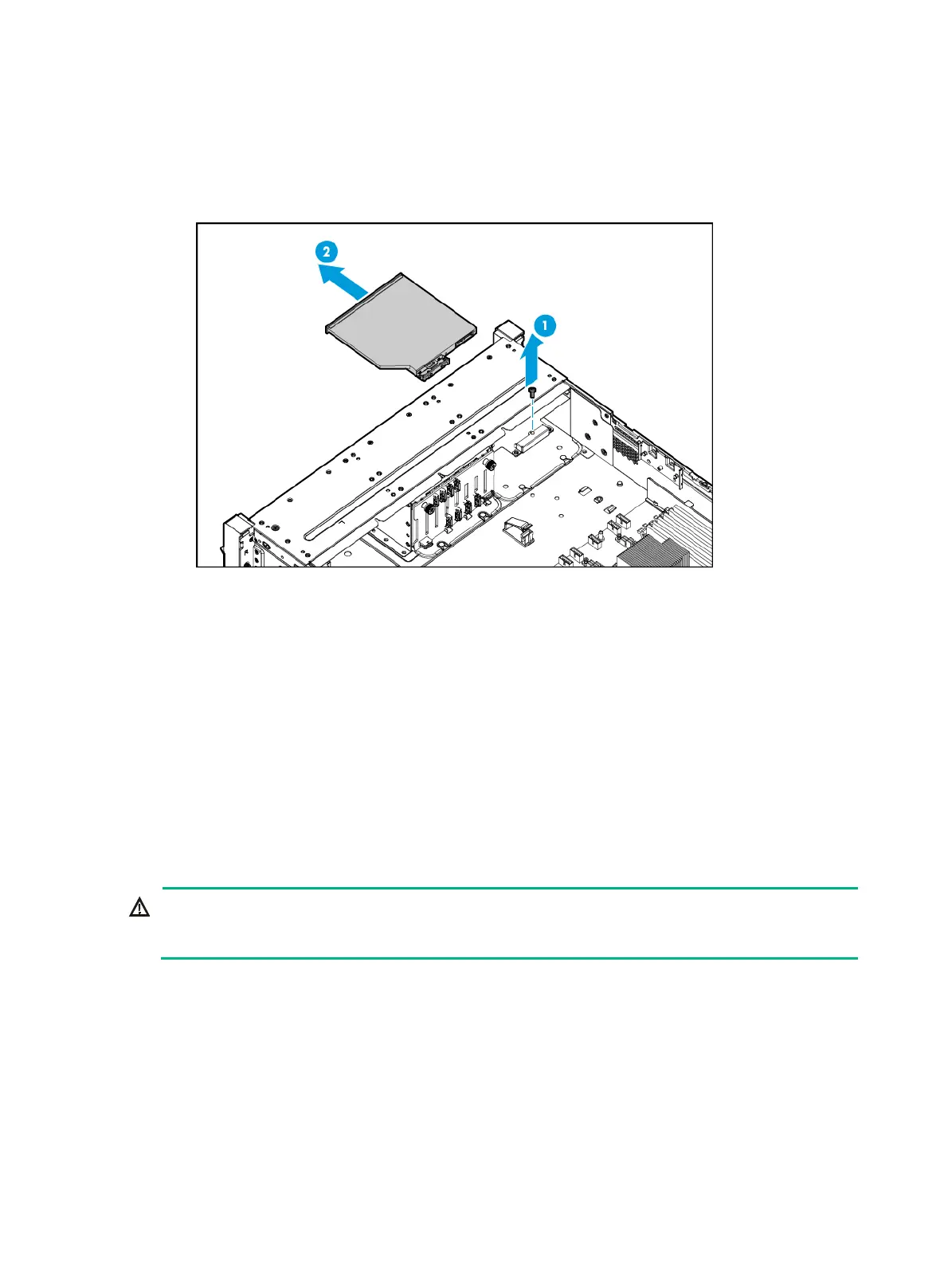
8. Remove the screw that secures the optical drive, and then push the optical drive out of the slot
from the inside of the chassis, as shown in Figure 155.
Figure 155
Removing the SATA optical drive
9. Install a new SATA optical drive. For more information, see "Installing a SATA optical drive."
10. Connect the optical drive cable.
11. Install the removed security bezel. For more information, see "Replacing the security bezel."
12. Install the fan cage. For more information, see "Replacing the fan cage."
13. Install the ch
assis air baffle. For more information, see "Installing air baffles."
14. Install the access panel. For more information, see "Installing the access panel."
15. Rack-mount the server. For more information, see "Rack-mounting the server."
16. Con
nect the power cord. For more information, see "Connecting the power cord."
17. Powe
r on the server. For more information, see "Powering on the server."
Replacing the chassis-open alarm module
WARNING!
To avoid bodily injury from hot surfaces, allow the server and its internal modules to cool before
touching them.
The server supports the following types of chassis-open alarm modules:
• Independent chassis-open alarm module.
• Chassis-open alarm module attached to the left chassis ear (with VGA and USB 2.0
connectors).
Removing the chassis-open alarm module
1. Power off the server. For more information, see "Powering off the server."
2. Remove the server from the rack. For more information, see "Removing the server from a rack."

 Loading...


