119
3. Remove the access panel. For more information, see "Removing the access panel."
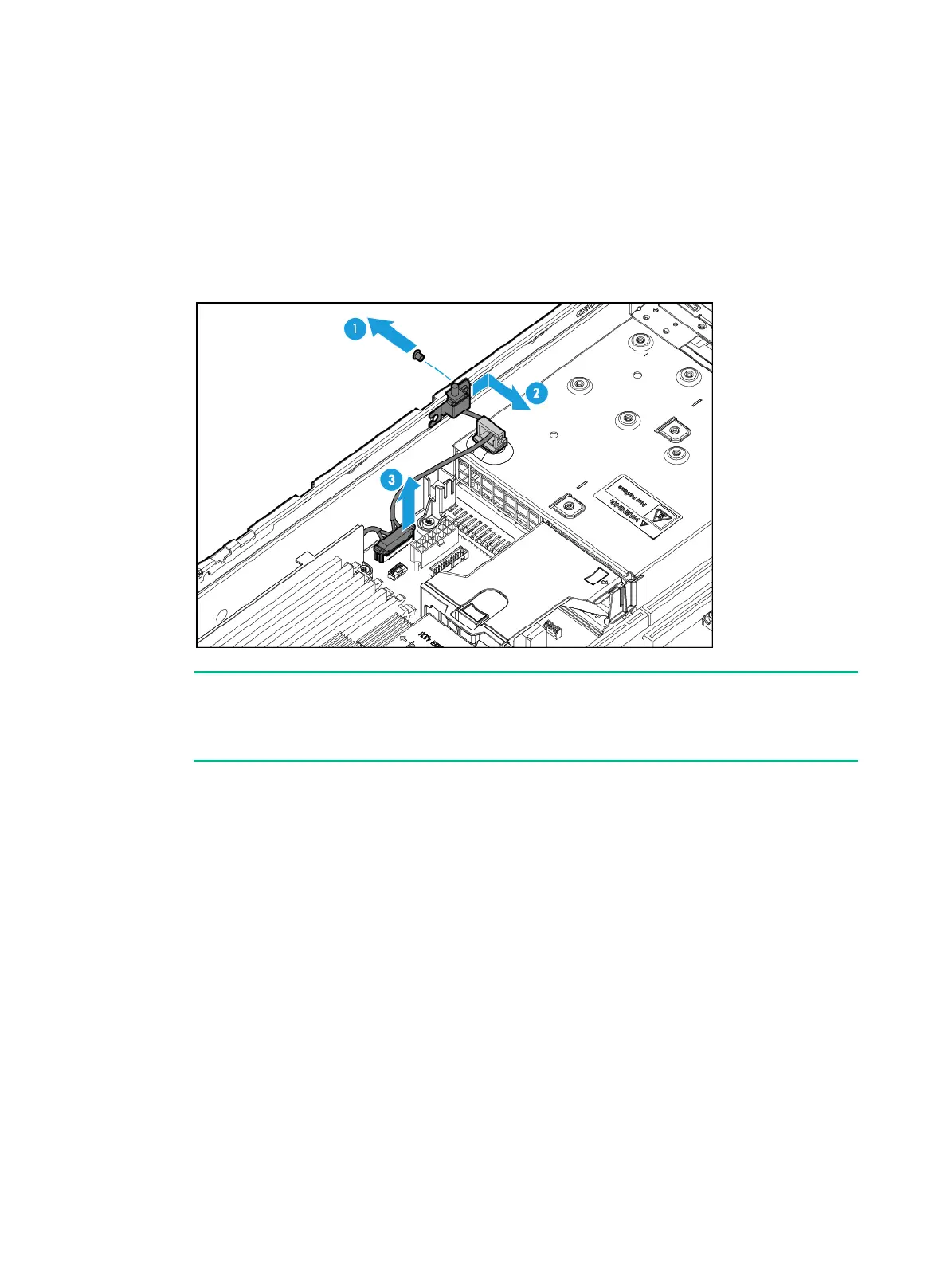
4. Remove the chassis-open alarm module:
a. Remove the screw that secures the chassis-open alarm module. Slide the module toward
the rear of the server chassis to disengage the keyed slot in the module from the peg on the
chassis, and pull the module out of the chassis, as shown by callouts 1 and 2 in Figure 156.
b. Disco
nnect the chassis-open alarm module cable from the chassis-open alarm module,
front VGA, and USB 2.0 connector on the system board, as shown by callout 3 in Figure
156.
Figure 156
Removing the chassis-open alarm module
NOTE:
The removal procedure is the same for the independent chassis-open alarm module and the
chassis-open alarm module attached to the left chassis ear. This figure uses the chassis-open
alarm module attached to the left chassis ear as an example.
5. Remove the left chassis ear if the chassis-open alarm module is attached to the left chassis ear.
For more information, see "Removing the left chassis ear."
Installing the chassis-open alarm module
1. Install the left chassis ear if the chassis-open alarm module is attached to the left chassis ear.
For more information, see "Installing the left chassis ear."
2. Install the ch
assis-open alarm module:
a. Connect the chassis-open alarm module cable to the chassis-open alarm module, front
VGA, and USB 2.0 connector on the system board, as shown by callout 1 in Figure 157.
b. Press the module again
st the chassis inside, with the notch of the keyed slot in the module
aligned with the peg on the chassis.
c. Slide the module toward the server front to lock the module into place, and then fasten the
screw, as shown by callouts 2 and 3 in Figure 157.

 Loading...


