160
GPU modules
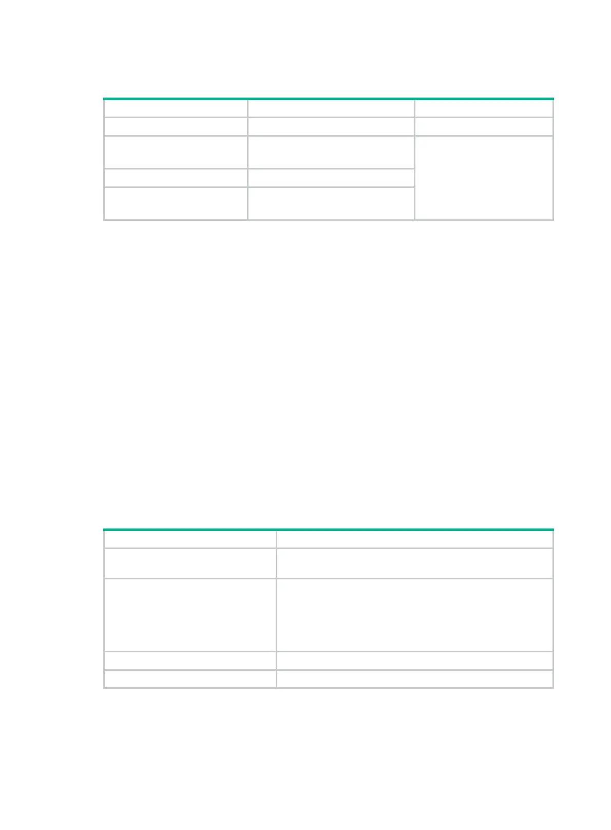
GPU module model Form factor Power cord
UIS-GPU-P4 LP, single-wide N/A
UIS-GPU-M60-1
UIS-GPU-M60-2-F
FH3/4FL, dual-slot wide
1
UIS-GPU-P40 FH3/4FL, dual-slot wide
UIS-GPU-M10
UIS-GPU-M10-1-F
FH3/4FL, dual-slot wide
Riser cards
To expand the server with PCIe modules, you can install riser cards on the PCIe riser connectors.
Riser connector 1 is for processor 1, riser connectors 2 and 3 are for processor 2.
The PCIe slots in a riser card are numbered differently depending on the riser card model and the
PCIe riser connector that holds the riser card.
Riser card guidelines
Each PCIe slot in a riser card can supply a maximum of 75 W power to the PCIe module. You must
connect a separate power cord to the PCIe module if it requires more than 75 W power.
Riser cards for riser connector 1 or 2
If a riser card can be installed on riser connector 1 or 2, the slot numbers of its PCIe slots are
presented in the m/n format in this document.
• The m argument represents the PCIe slot number on connector 1.
• The n argument represents the PCIe slot number on connector 2.
For example, PCIe slot 2/5 represents that a PCIe slot is numbered 2 or 5 when the riser card is
installed on riser connector 1 or riser connector 2, respectively.
UIS-RS-3*FHHL-F
Item Specifications
PCIe riser connector
• Connector 1
• Connector 2
PCIe slots
• Slot 1/4: PCIe3.0 ×16 (8, 4, 2, 1)
• Slot 2/5: PCIe3.0 ×16 (8, 4, 2, 1)
• Slot 3/6: PCIe3.0 ×8 (8, 4, 2, 1)
NOTE:
The numbers in parentheses represent link widths.
Form factors of PCIe modules FHHL
Maximum power supplied per PCIe slot 75 W

 Loading...


