49
• A PCIe slot can supply power to the installed PCIe module if the maximum power consumption
of the module does not exceed 75 W. If the maximum power consumption exceeds 75 W, a
power cord is required.
• Make sure the PCIe module is compatible with the riser card that carries the module. For more
information about PCIe module and riser card compatibility, see "Riser cards."
• The installation procedure and requirements vary by riser card model. Use Table 6 to identify
the installatio
n procedure, requirements, and applicable PCIe riser connectors for each riser
card.
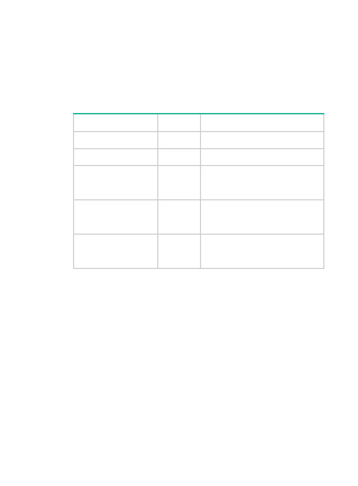
Table 6 Riser card installation location
Riser card model
PCIe riser
connector
Installation procedure
UIS-RS-3*FHHL-F 1 or 2
Installing a UIS-RS-3*FHHL-F riser card and a
PCIe module
UIS-RC-GPU/FHHL-2U-G3-F1 1 or 2
Installing a UIS-RC-GPU/FHHL-2U-G3-F1 riser
card an
d a PCIe module
UIS-RC-FHHL-2U-G3-F 3
Installing a UIS-RC-FHHL-2U-G3-F riser card
and a PCIe m
odule
NOTE:
A riser card bracket is required.
UIS-RC-2*LP-2U-G3-F 3
Installing a UIS-RC-2*LP-2U-G3-F riser card and
a PCIe modu
le
NOTE:
A riser card bracket is required.
UIS-RC-GPU/FHHL-2U-G3-F 3
Installing a UIS-RC-GPU/FHHL-2U-G3-F riser
card an
d a PCIe module
NOTE:
A riser card bracket is required.
Installing a UIS-RS-3*FHHL-F riser card and a PCIe module
1. Power off the server. For more information, see "Powering off the server."
2. Remove the server from the rack. For more information, see "Removing the server from a rack."
3. Remove the
access panel. For more information, see "Removing the access panel."
4. Remove the
screws from the riser card blank in PCIe riser connector 1 or 2, and then lift the
blank to remove it from the connector, as shown in Figure 63. Thi
s example uses PCIe riser
connector 1 to show the installation procedure.

 Loading...


