120
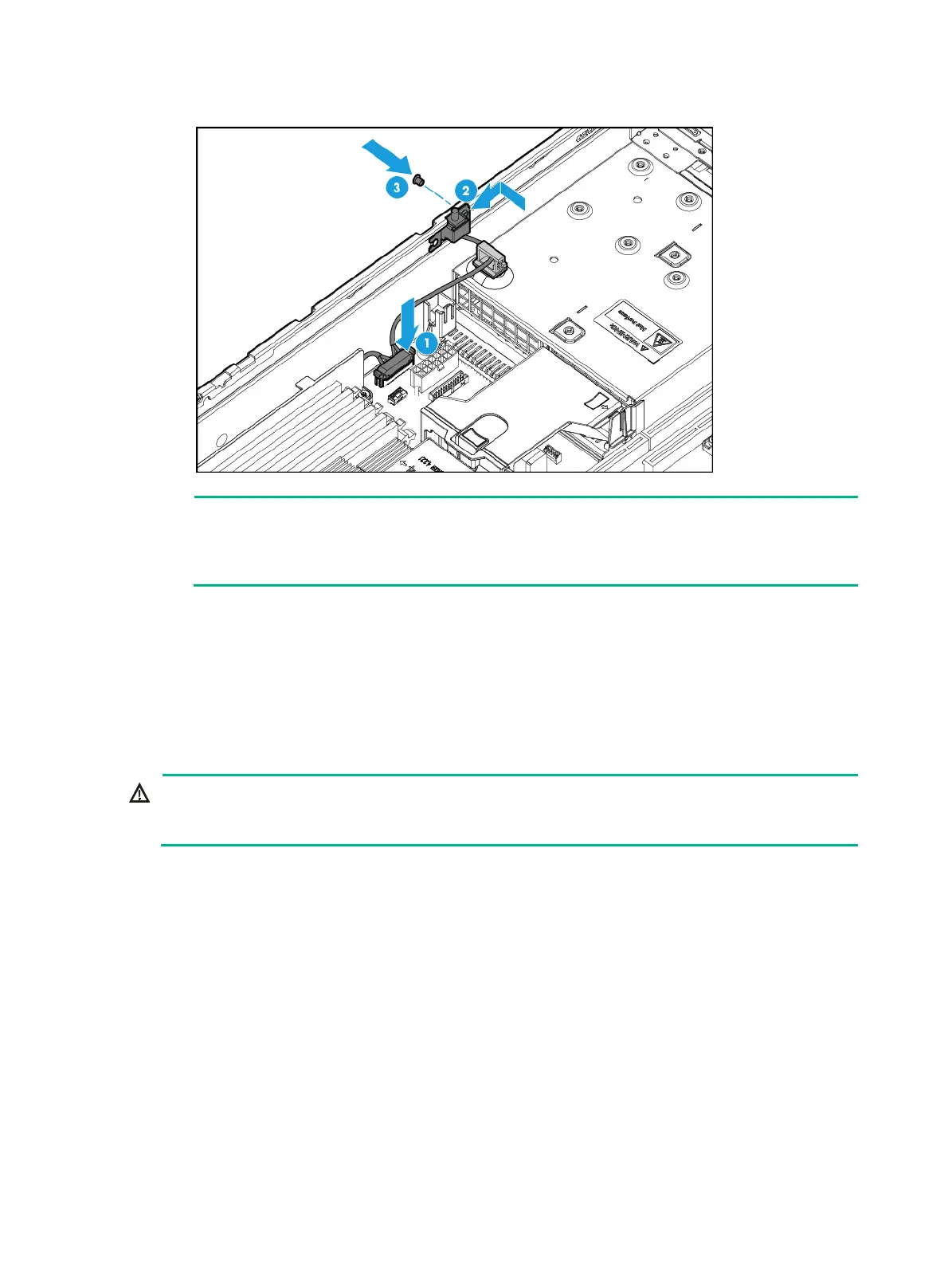
Figure 157 Installing the chassis-open alarm module
NOTE:
The installation procedure is the same for the independent chassis-open alarm module and the
chassis-open alarm module attached to the left chassis ear. This figure uses the chassis-open
alarm module attached to the left chassis ear as an example.
3. Install the access panel. For more information, see "Installing the access panel."
4. Rack-mount the server. For more information, see "Rack-mounting the server."
5. Con
nect the power cord. For more information, see "Connecting the power cord."
6. Powe
r on the server. For more information, see "Powering on the server."
Replacing chassis ears
WARNING!
To avoid bodily injury from hot surfaces, allow the server and its internal modules to cool before
touching them.
Replacing the right chassis ear
Removing the right chassis ear
1. Power off the server. For more information, see "Powering off the server."
2. Remove the server from the rack. For more information, see "Removing the server from a rack."
3. Remove the
access panel. For more information, see "Removing the access panel."
4. Remove the
chassis air baffle. For more information, see "Removing air baffles."
5. Remove the f
an cage. For more information, see "Replacing the fan cage."
6. Remove the
right chassis ear:
a. Disconnect the front I/O component cable assembly from the system board, as shown
in Figure 158.

 Loading...


