73
d. Connect the SATA M.2 SSD cable to the system board. For more information, see
"Connecting the SATA M.2 SSD cable."
11. (Optional.) Install the removed security bezel. For more information, see "Installing the security
bezel."
12. Install the re
moved fan cage. For more information, see "Installing fans."
13. Install the removed chassis air baffle. For more information, see "Installing air baffles."
14. Install the access pan
el. For more information, see "Installing the access panel."
15. Rack-mount the server. For more information, see "Rack-mounting the server."
16. Con
nect the power cord. For more information, see "Connecting the power cord."
17. Powe
r on the server. For more information, see "Powering on the server."
Installing an optical drive
Preparing for the installation
Use Table 8 to determine the location of the optical drive you are installing depending on the type of
the optical drive.
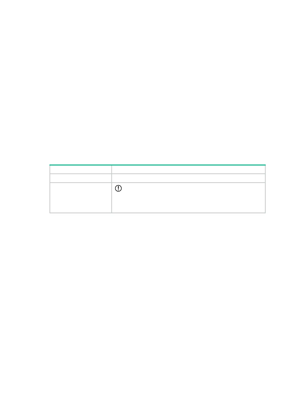
Table 8 Optical drive installation locations
Optical drive Installation location
USB 2.0 optical drive Connect the optical drive to a USB 2.0 or USB 3.0 connector on the server.
SATA optical drive
IMPORTANT:
Only the UIS-Cell 3010 G3 server supports the SATA optical drive.
Install the optical drive in drive cage bay 1 of the UIS-Cell 3010 G3 server.
For the location of drive cage bay 1, see "Front panel view."
Installing a SATA optical drive
1. Power off the server. For more information, see "Powering off the server."
2. Remove the server from the rack. For more information, see "Removing the server from a rack."
3. Remove the
access panel. For more information, see "Removing the access panel."
4. Remove the
chassis air baffle. For more information, see "Removing air baffles."
5. Remove the f
an cage. For more information, see "Replacing the fan cage."
6. Remove the
security bezel, if any. For more information, see "Replacing the security bezel."
7. Remove the screws that secure the drive cage bay blank over drive cage bay 1, and then push
the blank from the inside of the chassis to remove it, as shown in Figure 102.

 Loading...


