66
As a best practice, choose the PCIe riser connector for a GPU module as follows:
• Install the GPU module in the riser card on PCIe riser connector 1 if only one GPU module is
required.
• Install one GPU module in the riser card on PCIe riser connector 1 and the other in the riser
card on PCIe riser connector 2 if two GPU modules are required.
Installing a GPU module without a power cord
To install a UIS-GPU-M60-1 GPU module, make sure all the six fans are present before you power
on the server.
The procedure is the same for installing a GPU module in riser cards on PCIe riser connectors 1, 2,
and 3. This section uses the riser card on PCIe riser connector 1 as an example.
Procedure
1. Determine the installation position.
2. Power off the server. For more information, see "Powering off the server."
3. Remove the server from the
rack. For more information, see "Removing the server from a rack."
4. Remove the
access panel. For more information, see "Removing the access panel."
5. Remove the
PCIe riser card blank from PCIe riser connector 1, as shown in Figure 63.
6. Attach the G
PU module to the riser card.
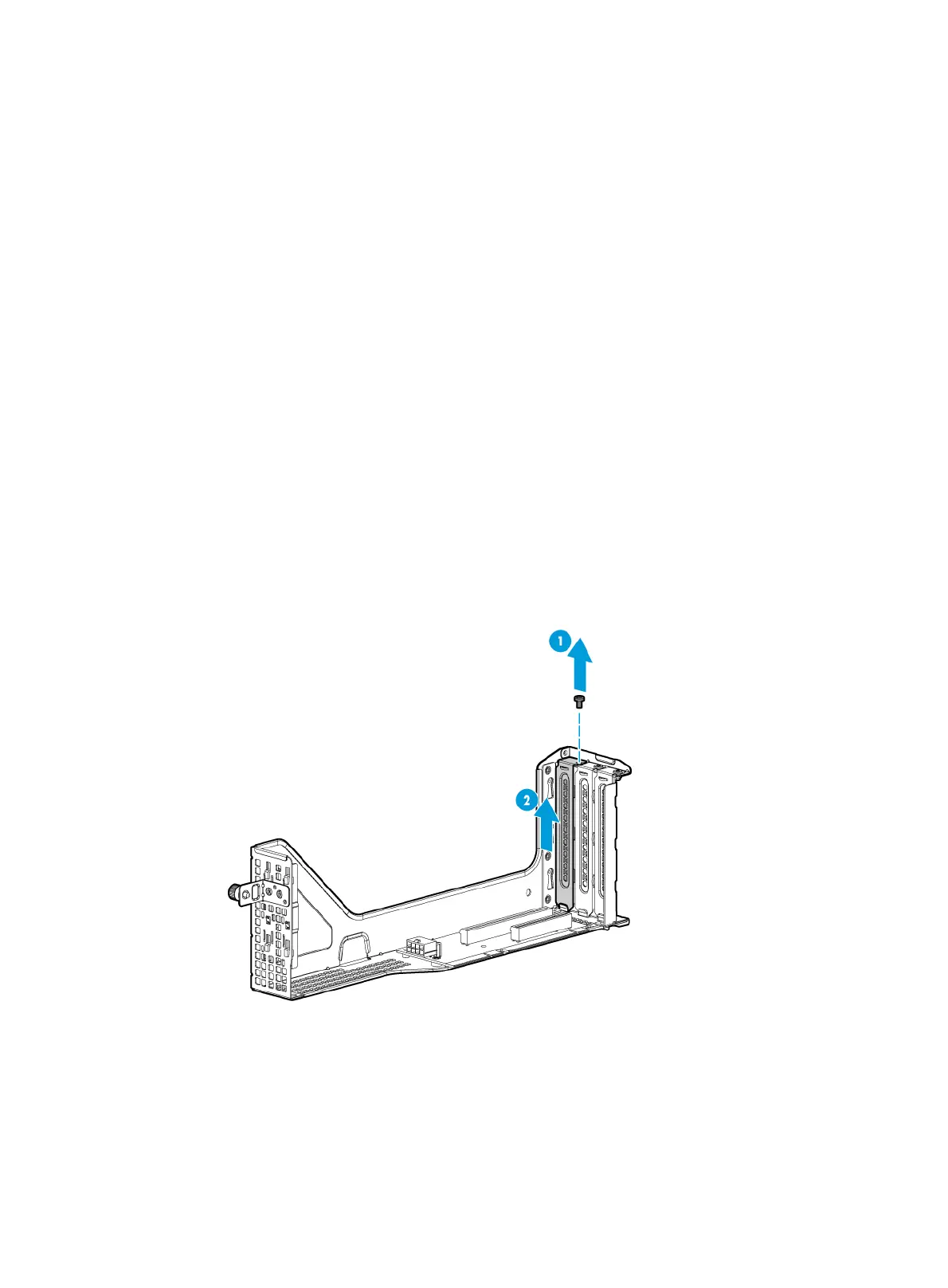
a. Remove the screw from the target PCIe slot, and then pull the blank out of the slot, as
shown in Figure 93.
Figure 93
Removing the PCIe module blank
b. Insert the GPU module into the PCIe slot along the guide rails and fasten the screw to
secure the module into place, as shown in Figure 94.

 Loading...


