150
System maintenance switches
Use the system maintenance switches to configure the basic server or HDM settings if you cannot
access HDM or manage the server from HDM, as described in Table 19. T
o identify the location of
the switches on the system board, see Figure 193.
Table 19
System maintenance switches
Item Description
System
maintenance
switch 1
• Pins 1-2 jumped (default)—HDM login requires the username and password of a
valid HDM user account.
• Pins 2-3 jumped—HDM login requires the default username and password.
System
maintenance
switch 2
• Pins 1-2 jumped (default)—Normal server startup.
• Pins 2-3 jumped—Clears all passwords from the BIOS at server startup.
System
maintenance
switch 3
• Pins 1-2 jumped (default)—Normal server startup.
• Pins 2-3 jumped—Restores the default BIOS settings. For this purpose, jump pins 2
and 3 for over 30 seconds and then jump pins 1 and 2 for normal server startup.
DIMM slots
The server provides 6 DIMM channels per processor, 12 channels in total. Each channel contains
one white-coded slot and one black-coded slot, as shown in Table 20.
Table 20
DIMM slot numbering and color-coding scheme
Processor DlMM slots
Processor 1
A1 through A6 (white coded)
A7 through A12 (black coded)
Processor 2
B1 through B6 (white coded)
B7 through B12 (black coded)
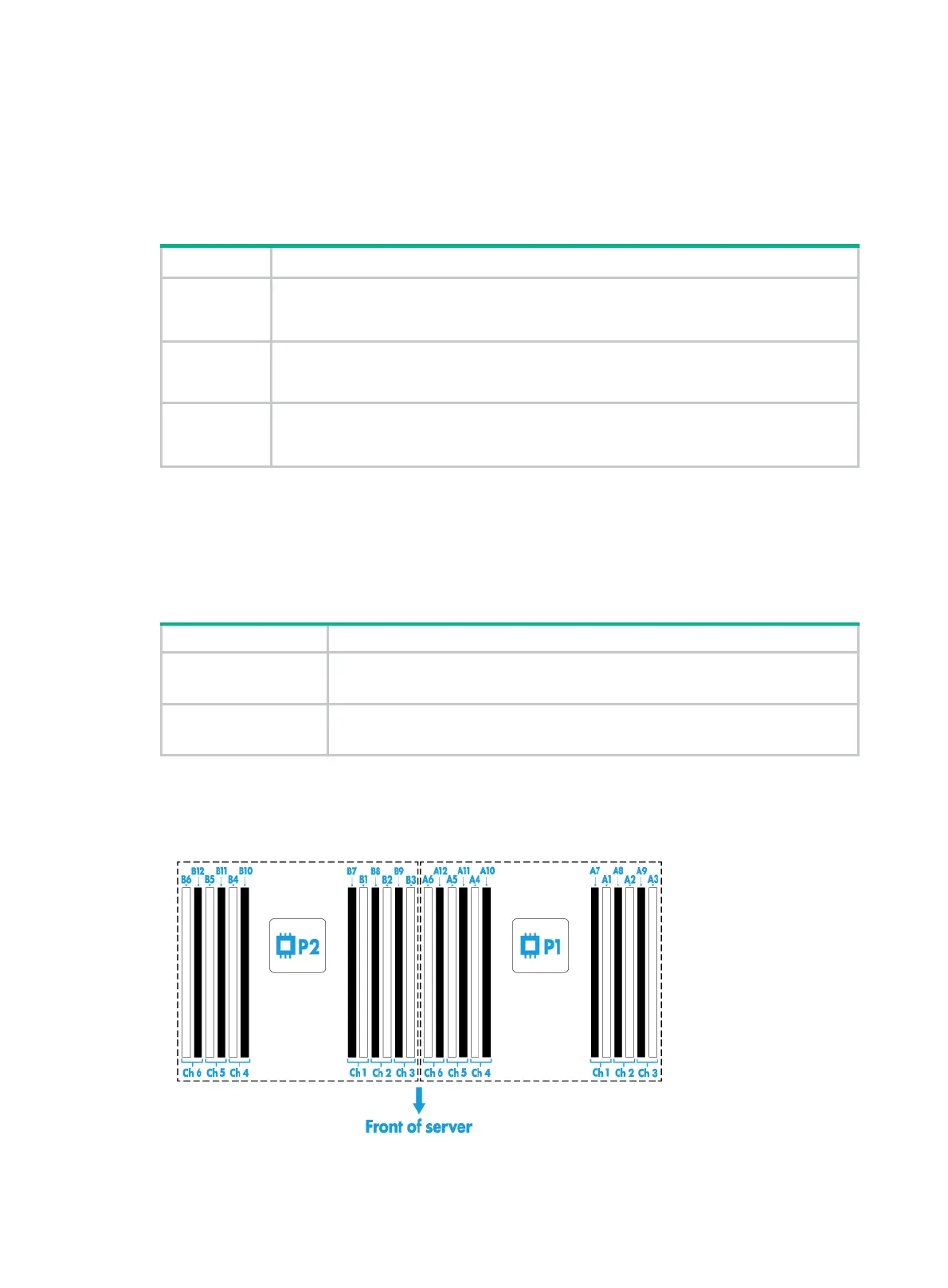
Figure 194 shows the physical layout of the DIMM slots on the system board. For more information
about the DIMM slot population rules, see the guidelines in "Installing DIMMs."
Figure 194 DIMM physical layout

 Loading...


