123
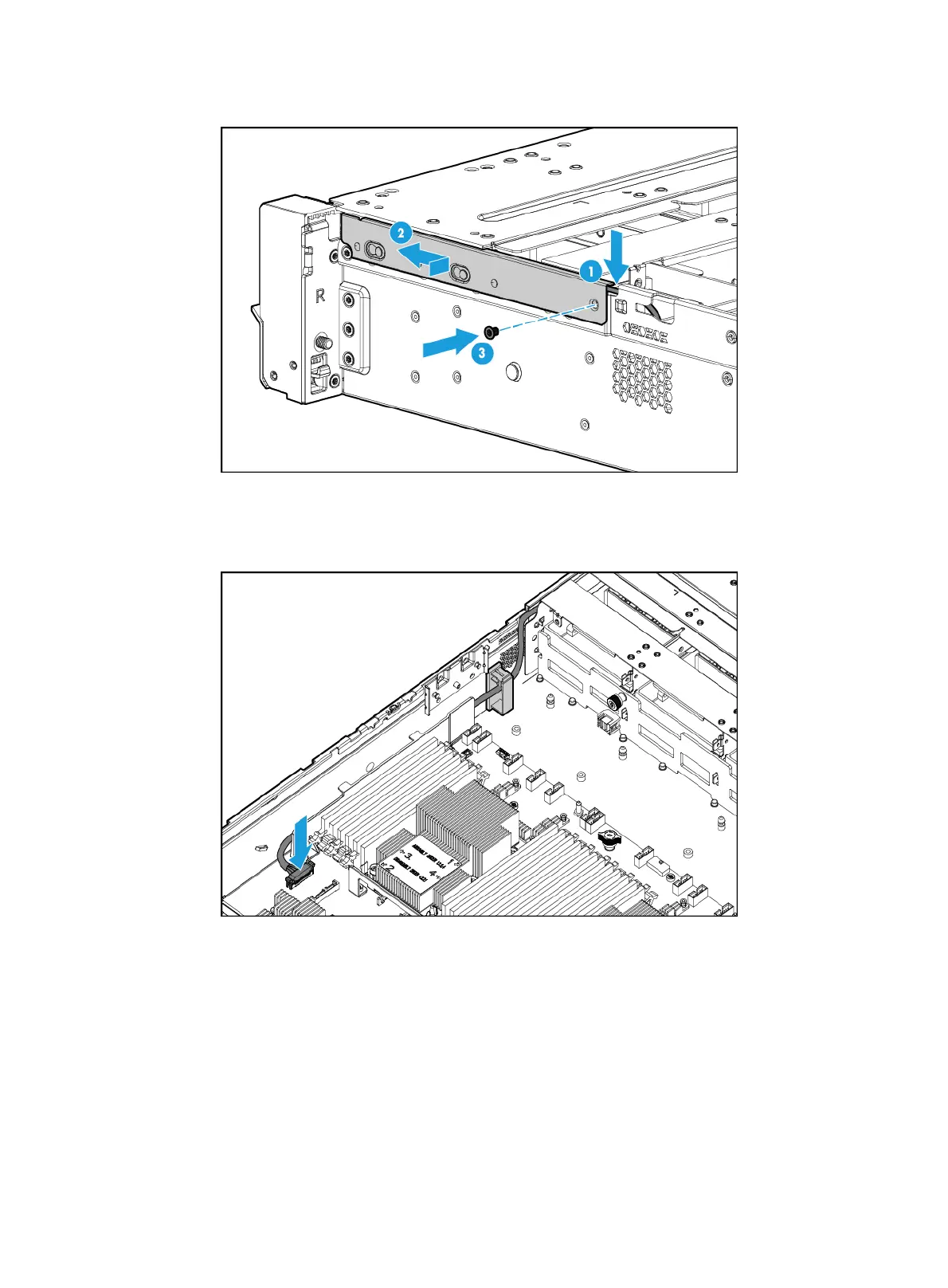
Figure 162 Installing the cable protection plate
b. Connect the front I/O component cable assembly to the front I/O connector on the system
board, as shown in Figure 163.
Figure 163
Connecting the front I/O component cable assembly
3. Install the fan cage. For more information, see "Replacing the fan cage."
4. Install the chassis air baffle. For more information, see "Installing air baffles."
5. Install the access panel. For more information, see "Installing the access panel."
6. Rack-mount the server. For more information, see "Rack-mounting the server."
7. Con
nect the power cord. For more information, see "Connecting the power cord."
8. Powe
r on the server. For more information, see "Powering on the server."
Replacing the left chassis ear
The server supports the following types of left chassis ears:

 Loading...


