122
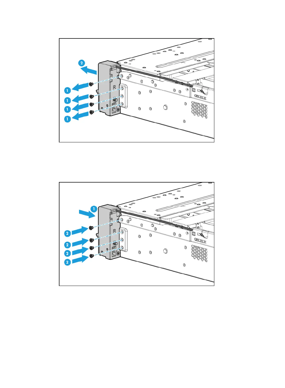
Figure 160 Removing the right chassis ear
Installing the right chassis ear
1. Attach the right chassis ear to the right side of the server, and use screws to secure it into place,
as shown in Figure 161.
Figure 161
Installing the right chassis ear
2. Connect the front I/O component cable assembly:
a. Insert the front I/O component cable assembly into the cable cutout, as shown by callout 1
in Figure 162.
b. Attach the ca
ble protection plate to the chassis front of the server, with its keyed slots over
the pegs on the chassis.
c. Slide the plate toward the server front to lock it onto the pegs, as shown by callout 2
in Figure 162.
d. Fasten th
e plate with its screw, with the front I/O LED cable (round cable) above the screw
and the USB 3.0 connector cable (flat cable) below the screw, as shown by callout 3
in Figure 162.

 Loading...


