51
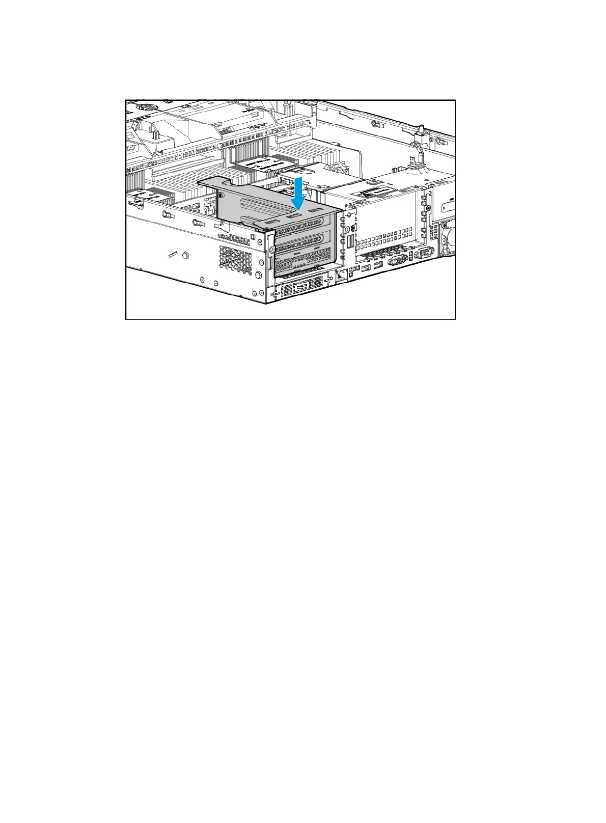
6. Insert the riser card in the PCIe riser connector, as shown in Figure 66.
Figure 66 Installing the riser card
7. Connect PCIe module cables, if any.
8. Install the access panel. For more information, see "Installing the access panel."
9. Rack-mount the server. For more information, see "Rack-mounting the server."
10. Con
nect the power cord. For more information, see "Connecting the power cord."
11. Powe
r on the server. For more information, see "Powering on the server."
Installing a UIS-RC-GPU/FHHL-2U-G3-F1 riser card and a
PCIe module
1. Power off the server. For more information, see "Powering off the server."
2. Remove the server from the rack. For more information, see "Removing the server from a rack."
3. Remove the
access panel. For more information, see "Removing the access panel."
4. Remove the
screws from the riser card blank in PCIe riser connector 1 or 2, and then lift the
blank until it is unseated from the connector, as shown in Figure 67. This exampl
e uses PCIe
riser connector 2 to show the installation procedure.

 Loading...


