68
Verifying the installation
Log in to HDM to verify that the GPU module is operating correctly. For more information, see HDM
online help.
Installing a GPU module with a power cord
To install a UIS-GPU-M60-1 GPU module, make sure all the six fans are present before you power
on the server.
The procedure is the same for installing a GPU module in riser cards on PCIe riser connectors 1, 2,
and 3. This section uses GPU-M4000-1 GPU module and PCIe riser connector 1 as an example.
Procedure
1. Determine the installation position.
2. Power off the server. For more information, see "Powering off the server."
3. Remove the server from the
rack. For more information, see "Removing the server from a rack."
4. Remove the
access panel. For more information, see "Removing the access panel."
5. Remove the
PCIe riser card blank from PCIe riser connector 1, as shown in Figure 63.
6. Remove the
screw from the target PCIe slot, and then pull the blank out of the slot, as shown
in Figure 93.
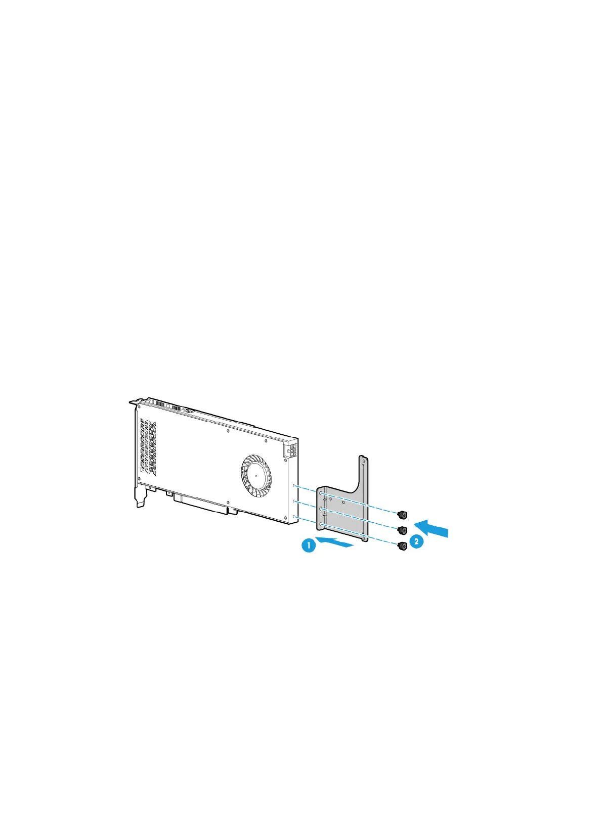
7. Attach the su
pport bracket provided with the GPU module to the GPU module. As shown
in Figure 96, align screw h
oles in the support bracket with the installation holes in the GPU
module, and use screws to attach the support bracket to the GPU module.
Figure 96 Installing the GPU module support bracket
8. Install the GPU module and connect the GPU module power cord, as shown in Figure 97:
a. Connect the GPU power end of power cord to the GPU module, as shown by callout 1.
b. Insert the GPU module into the PCIe slot along the guide rails, as shown by callout 2.
c. Connect the other end of the power cord to the riser card and use the screw to secure the
GPU module into place, as shown by callouts 3 and 4.

 Loading...


