163
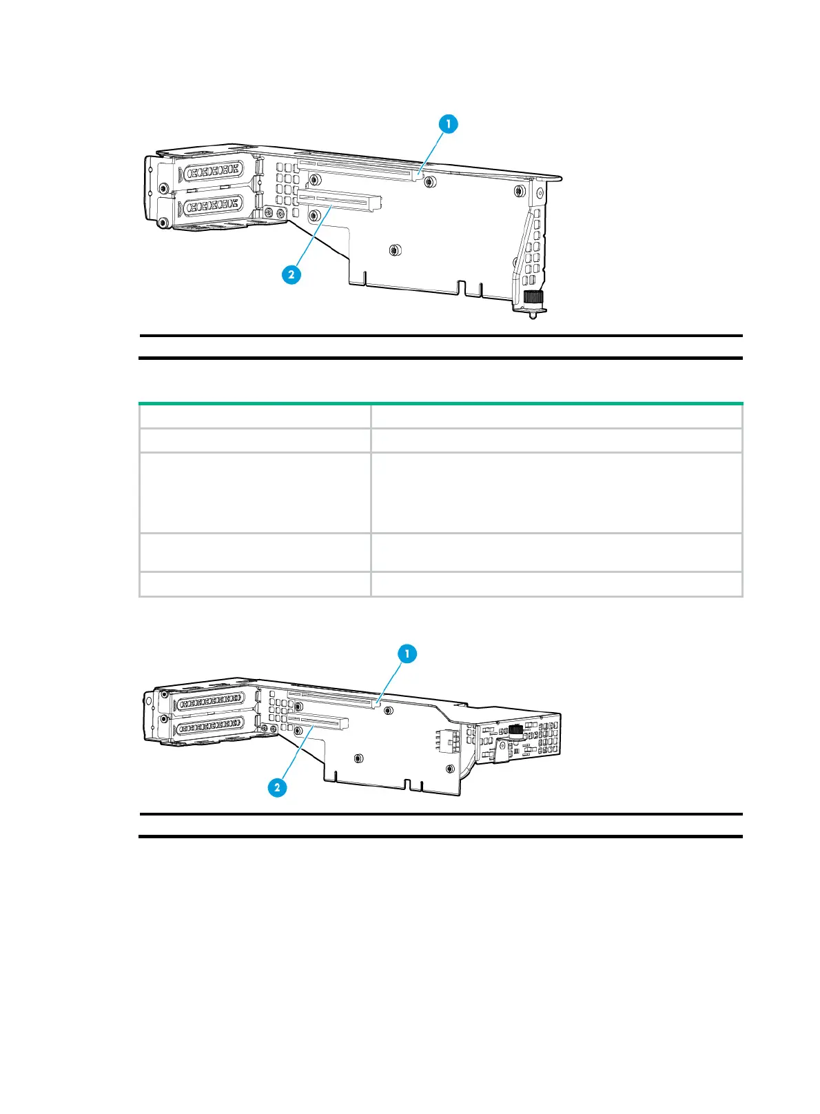
Figure 205 PCIe slots on the UIS-RC-2*LP-2U-G3-F riser card
(1) PCIe slot 7 (2) PCIe slot 8
UIS-RC-GPU/FHHL-2U-G3-F
Item Specifications
PCIe riser connector Connector 3
PCIe slots
• Slot 7: PCIe3.0 ×16 (16, 8, 4, 2, 1)
• Slot 8: PCIe3.0 ×8 (8, 4, 2, 1)
NOTE:
The numbers in parentheses represent link widths.
Form factors of PCIe modules
FHHL (only slot 7 supports single-wide and double-wide GPU
modules)
Maximum power supplied per PCIe slot 75 W
Figure 206 PCIe slots on the UIS-RC-GPU/FHHL-2U-G3-F riser card
(1) PCIe slot 7 (2) PCIe slot 8
Fans
The server supports a maximum of six hot swappable fans. Figure 207 shows the layout of the fans
in the chassis.

 Loading...


