86
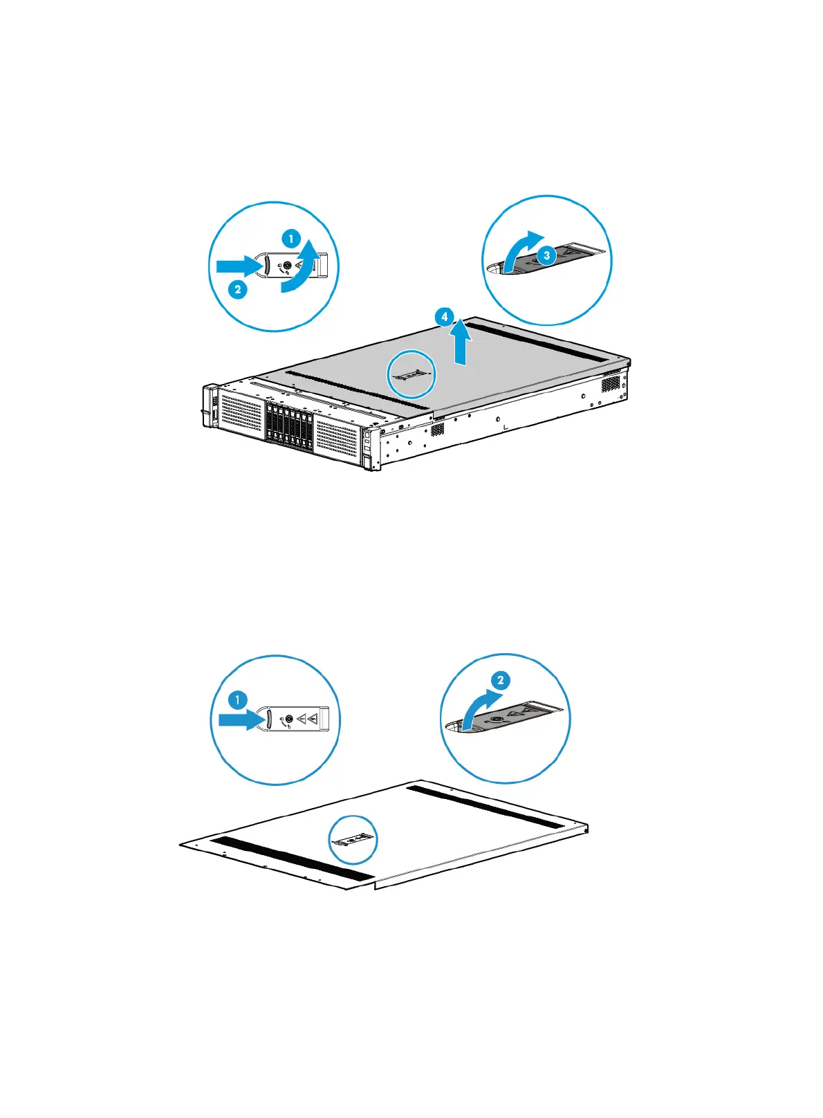
b. Press the latch on the locking lever, pull the locking lever upward, and then release the latch,
as shown by callouts 2 and 3 in Figure 117. The access panel will automatically slide to the
rea
r of the server chassis.
c. Lift the access panel to remove it, as shown by callout 4 in Figure 117.
Figure 117
Removing the access panel
Installing the access panel
1. Use a T15 Torx screwdriver to unlock the locking lever.
2. Press the latch on the locking lever, pull the lever upward, and then release the latch, as shown
in Figure 118.
Figure 118
Opening the locking lever
3. Install the access panel:
a. Place the access panel on top of the server chassis, with the guide pin in the chassis
aligned with the pin hole in the locking lever area, as shown by callout 1 in Figure 119.
b. Clo
se the locking lever, as shown by callout 2 in Figure 119. The a
ccess panel will
automatically slide toward the server front to secure itself into place.

 Loading...


