Note
The external power supply and the access control terminal should
use the same GND cable.
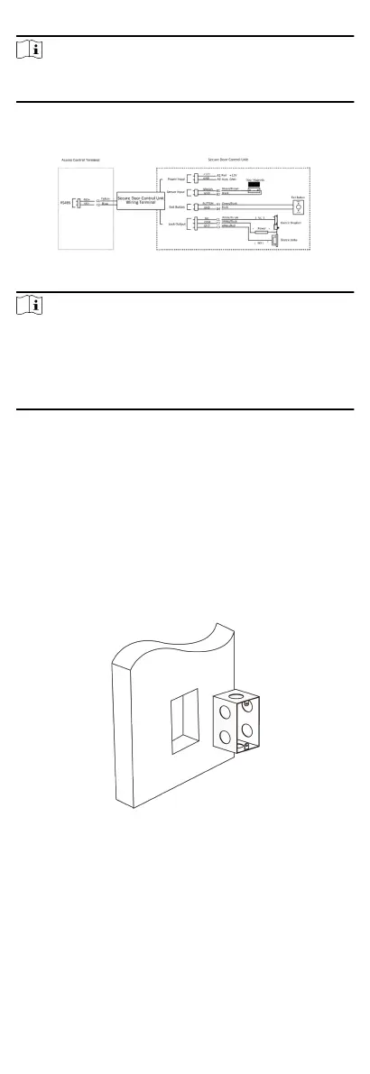
4.3 Secure Door Control Unit Wiring
The wiring diagram is as follows:
Figure 4-3 Secure Door Control Unit Wiring
Note
•
The external power supply and the secure door control unit
should use the same GND cable.
•
If you want to connect secure door control unit, you should set
the connecon mode as Connect Extension Module in the
RS-485
sengs in the client soware.
5 Installaon
Before You Start
•
Make sure that the device in the package is in good condion
and all the assembly parts are included.
•
Make sure that the wall is strong enough to withstand three
mes the weight of the device.
Steps
1.
Install 120 gang box into the wall.
Figure 5-1 Install Gang Box
2.
Route the cables through the cable hole of the mounng plate.
3.
Secure the device
mounng plate on the gang box with 2
screws (supplied).
7

 Loading...