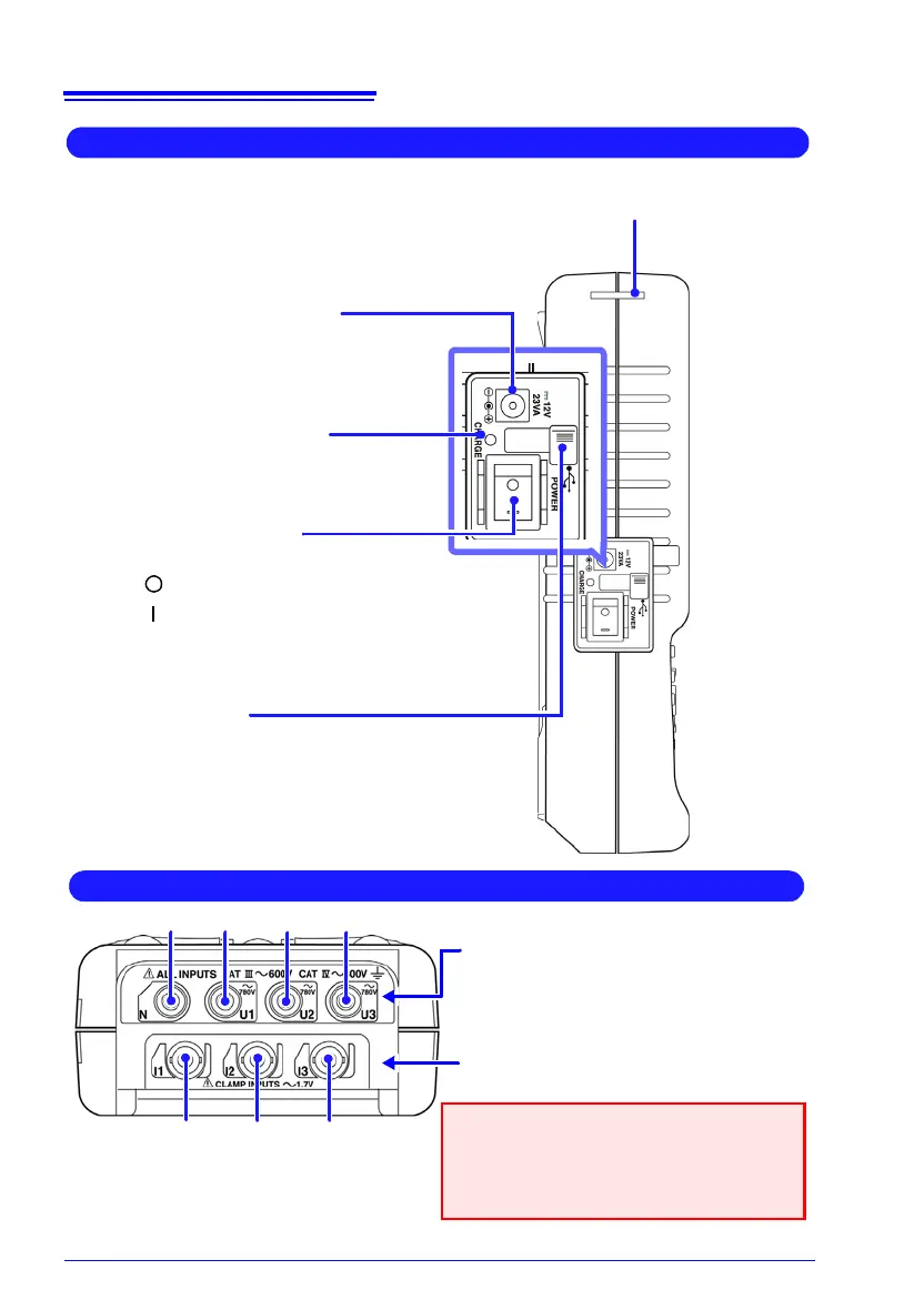
POWER Switch
Turns the instrument on and off.
(p. 46)
Power Off
Power On
Left Side
AC Adapter socket
Connect the supplied Model 9418-15
AC Adapter. (p. 41)
USB Port
(USB 2.0 mini-B receptacle)
Open the dust cap and connect the USB cable.
Connect to a computer to transfer data or operate
remotely. (p. 127)
CHARGE LED (red)
This LED lights when the battery is
charging. (p. 40)
Strap Hole
(p. 38)
Voltage Input Terminals (p. 42)
Connect the supplied Model L9438-55 Volt-
age Cord (voltage cords).
Top Panel
Current Input Terminals (p. 44)
Connect optional clamp sensors.
Apply one of the supplied input terminal la-
bels. (p. 37)
Attach the corresponding labels to the
clamp sensor and voltage cords. (p. 38)
N
I1 I3I2
U3U2U1