5.2 Connecting to the Lines to be Measured
83
5
Press the key to display the [WIRING] screen.
While looking at the diagram, pay attention to the colors of the input ter-
minals and leads.
These examples use the R S T phase names and TYPE 1 (HIOKI) phase
co
lors.
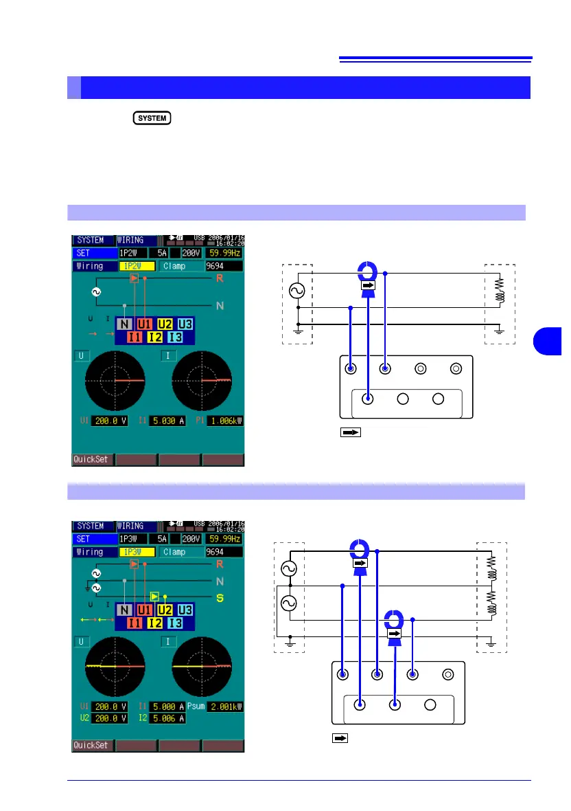
System Wiring Diagrams
NU1U2U3
I1 I2 I3
Source Side
Load Side
R
N
G
The arrows point toward the
load.
R:Line/ N: Neutral/ G: Ground
Single-Phase 2-Wire (1P2W)
NU1U2U3
I1 I2 I3
Source Side
Load Side
R
The arrows point toward the load.
R,S: Line/ N:Neutral/ G:Ground
N
S
G
Single-Phase 3-Wire (1P3W)