123
────────────────────────────────────────────────────
10.1 AC Four-terminal Method
────────────────────────────────────────────────────
1
2
3
4
5
6
7
8
9
10
11
12
13
14
15
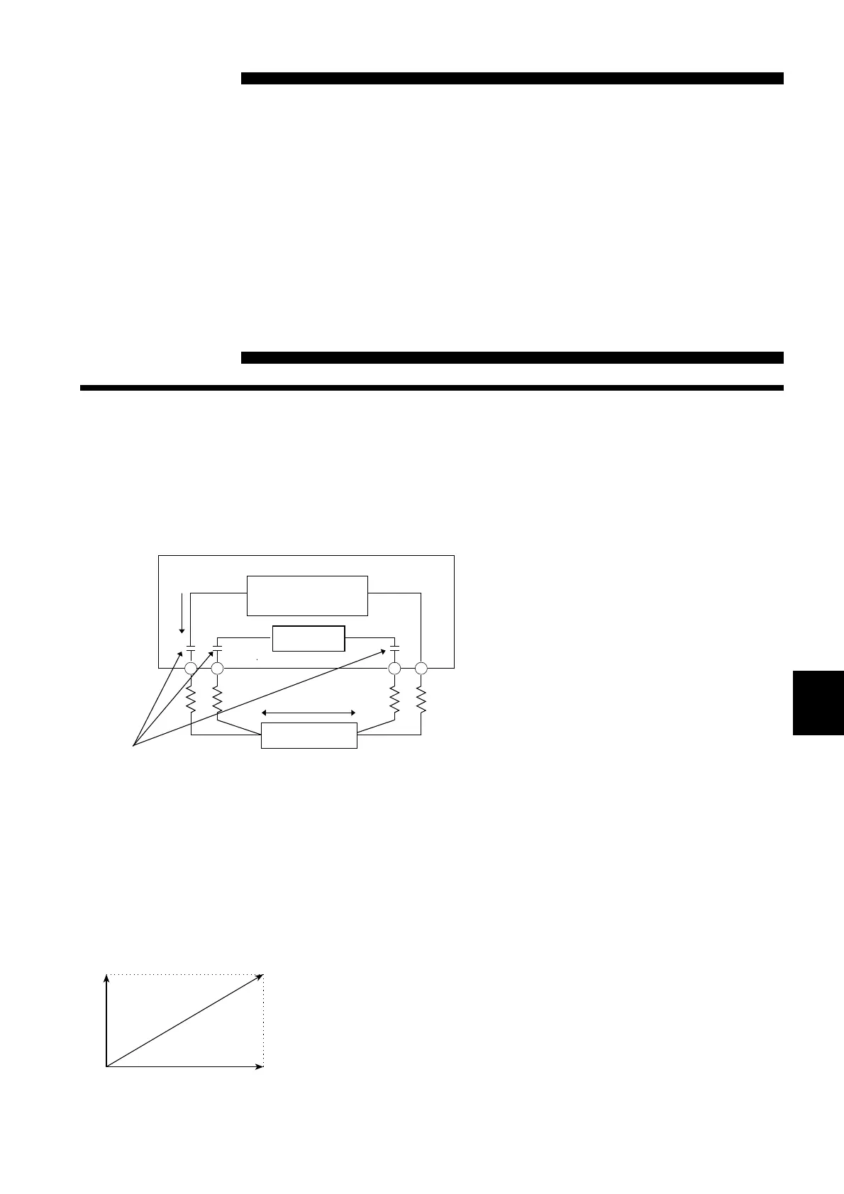
I
DC-eliminatio
capacitor
Constant curren
source
Voltmete
Resistance R
Resistance measurement circu
Values R1 to R4 are the resistances o
the measurement leads plus contact
Chapter 1
Useful Information an
Advanced Measureme
0.1 AC Four-terminal Method
The 3560 uses the AC four-terminal method, so that resistance
measurement can be carried out with the resistance of the leads and the
contact resistance between the leads and the object to be measured
canceled out. The following figure shows the principle of the AC four-
terminal measurement method.
An AC current (Is) is supplied from the
SOURCE terminals of the 3560 across the
tested battery.
The voltage drop across the internal
impedance of the battery (V
IS
)is
measured by the SENSE terminals. At
this point, since the SENSE terminals are
connected to an internal voltmeter with a
high impedance, almost no current flows
through the resistances R2 and R3 which
represent the lead resistances and contact
resistances.
As a result, there is almost no voltage
drop across the resistances R2 and R3.
Thus the voltage drop due to the lead
resistances and contact resistances is very
small, and these can be canceled out.
In the 3560, a synchronized wave detection system is used, whereby the
internal impedance is separated into resistance and reactance, and the
resistive component only displayed.
If the lead resistance, the contact resistance between
measured object and lead, or the contact resistance
between the lead and the 3560 instrument increases,
the 3560 can no longer supply normal current to the
measured object, resulting in an abnormal
measurement status indicated by "____" within the
measured resistance field. For more information on
abnormal measurements, see Section 4.5 "Starting
Measurement"