125
────────────────────────────────────────────────────
10.3 Configuration and Extension of the Measurement Leads
────────────────────────────────────────────────────
1
2
3
4
5
6
7
8
9
10
11
12
13
14
15
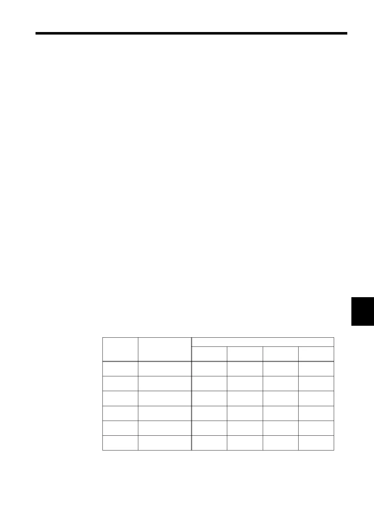
Resistance
range
(Ω)
Lead resistance
and contact
resistance
SENSE line break check / Voltage limiter
OFF/ON
(Ω)
OFF/ON
(Ω)
ON/OFF
(Ω)
ON/OFF
(Ω)
30 m
RC1+RL+RC2
RC2
1.4
900 m
400 m
400 m
1.4
300 m
400 m
300 m
300 m
RC1+RL+RC2
RC2
13
7.5
5
5
13
13
5
3.3
3
RC1+RL+RC2
RC2
125
76
55
55
130
34
55
34
30
RC1+RL+RC2
RC2
990
760
260
260
990
333
260
200*
300
RC1+RL+RC2
RC2
2.3 k
1.5 k
890
890
2.3 k
640
890
520*
3k
RC1+RL+RC2
RC2
8.7 k
5.1 k
3.9 k
3.9 k
8.7 k
1.9 k
3.9 k
330*
0.3 Configuration and Extension of the Measurement
Leads
Measurement lead extension is normally performed by Hioki. If you want
extension performed, contact your dealer or Hioki representative.
■ Observe the following points when extending measurement leads:
1. Use the thickest lead available. Extend the lead only by the necessary
amount.
2. Maintain the AC four-terminal configuration while extending the lead.
Changing the four-terminal configuration to a two-terminal
configuration can result in measurement data being affected by lead
resistance and/or contact resistance, resulting in inaccurate
measurement.
3. Make the branch section as short as possible. Try to extend the thick
lead instead.
4. Make sure the lead is insulated.
5. Try to maintain the same lead arrangement and configuration for both
zero-adjust and actual measurement.
6. Extending a lead increases the voltage drop in the lead. Do not exceed
the permissible resistance for the extended lead per range defined by
the 3560. Over-extending a lead can lead to resistance not being
measured to the maximum count (SLOW/MEDIUM: 31000 counts,
FAST: 3100 counts).
7. To prevent eddy currents from affecting measurement, keep
measurement leads away from metallic parts.
8. After the lead is extended, check it for operating capability, accuracy,
and the like.
■ Maximum lead extension (Figures provided in this table are for
reference only; their accuracy is not guaranteed.)
RL: Measurement object
RC1: "Hi" lead resistance + contact resistance
RC2: "Lo" lead resistance + contact resistance
*: RL = F.S.