131
────────────────────────────────────────────────────
10.8 Calibration of the 3560
────────────────────────────────────────────────────
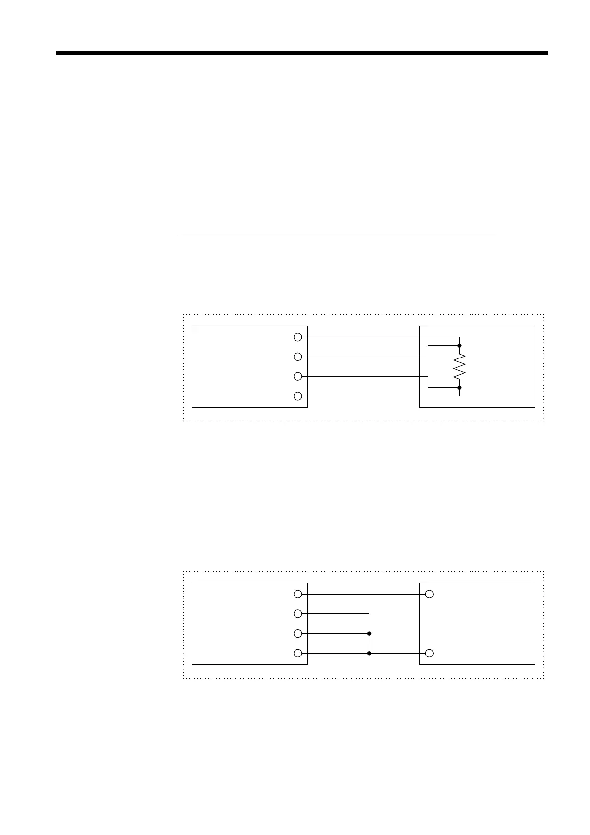
Standard resisto
DC generato
0.8 Calibration of the 3560
For the calibration environment, see 2.2 "Measurement Range."
■ Calibration of the Ohmmeter
・ Use the 9453 FOUR TERMINAL LEAD as the connection lead.
・ Use standard resistors with excellent temperature characteristics that
resist deterioration over time.
・ To prevent influence by the lead, use four-terminal resistors.
・ Use a resistor that will reflect the correct resistance at 1 kHz.
With
wire-wound resistors, the inductance element is so large that the pure
resistance (DC resistance) does not equal the effective resistance (real
part of impedance, displayed on the 3560).
・ For connection of a standard resistor to the 3560, see the figure below.
■ Calibration of the Voltmeter
・ Use the 9453 FOUR TERMINAL LEAD as the connection lead.
・ Use a generator that can output a DC voltage of 4.9 V or 49 V.
・ For connection of a generator to the 3560, see the figure below.
・ Do not apply an alternating current from the 3560 to the generator, as
the generator may malfunction.