17
────────────────────────────────────────────────────
────────────────────────────────────────────────────
1
2
3
4
5
6
7
8
9
10
11
12
13
14
A
Setting the comparator functions
Selecting the measurement mod
Setting the measurement range
Advanced setting
Starting measurement
Executing zero adjust
Sampling rate
Hold
Lead Line break chec
Zero clear
Key lock
Local
Buzzer
Voltage limiter
Preparing for Measurement
Chapter
Measurement Procedu
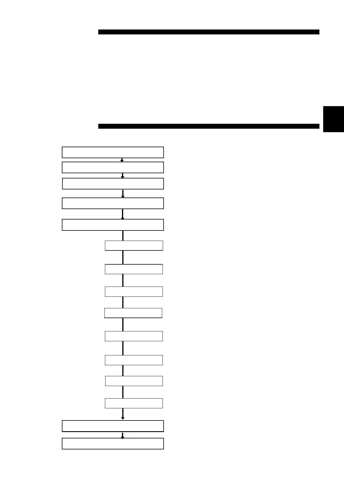
The following flowchart outlines a basic measurement sequence.
See Chapter 3
See Section 4.1
See Section 4.2
Set the comparator as necessary.
See Chapter 5
Set the "Advanced setting " as necessary.
Set the following parameter:
Select the desired sampling rate from FAST,
MEDIUM, and SLOW. See Section 4.3.1
In the comparator setting, you can set whether
the buzzer will sound. See Section 4.3.2
The measured value can be held.
See Section 4.3.3
A broken line wire check is executed for the
SENSE lines. See Section 4.3.4
Input voltage is limited to a maximum of 20
mVpeak. See Section 4.3.5
Zero-clear is a function used to return the zero-
adjust data to their default values. See Section
4.3.6
Keys may be locked to prevent improper setup.
See Section 4.3.7
Remote mode may be reset to local mode when
the instrument is remote-controlled through the
RS-232C or GP-IB interface. See Section 4.3.8
See Section 4.4
See Section 4.5