51
────────────────────────────────────────────────────
6.3 Measurement by External Control Terminal and External Output Terminal
────────────────────────────────────────────────────
.3.4 Internal Circuit Configuration (Input/Output)
NOTE
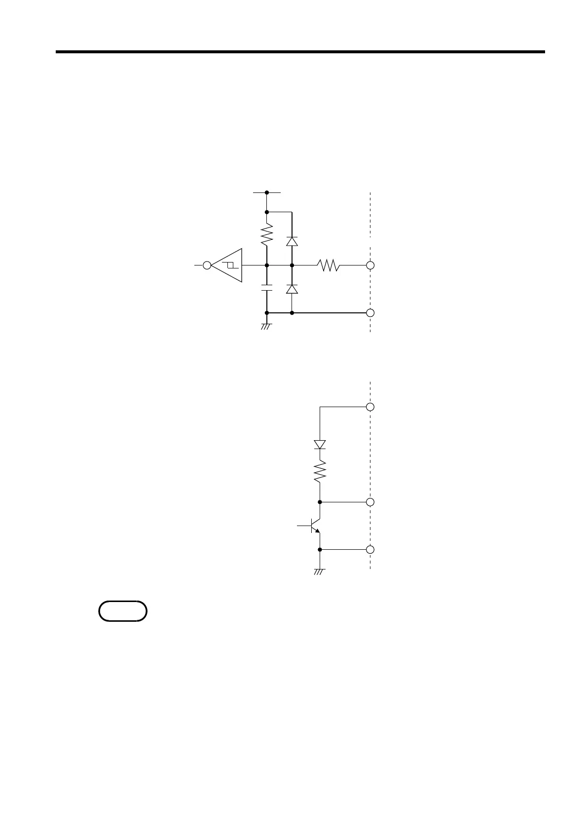
These respective charts illustrate the circuit configuration of the external
control terminal (input) and the external output terminal (output). The
external control terminal operates at the CMOS level.
■ Circuit configuration of the external control terminal
■ Circuit configuration of the external output terminal
Signal leads are functionally separate from measurement leads in order
to prevent interaction between these lead groups. To preserve the
insulation, be sure to ground the equipment if it’s connected to the 3560.