38
────────────────────────────────────────────────────
5.5 Switching On/Off the Comparator
────────────────────────────────────────────────────
NOTE
Comparator output (Resistance measurement mode)
Resistance Hi(Red) IN(Green) Lo(Red)
Comparator output (Resistance/voltage measurement mode)
Resistanc
Voltage
Hi IN Lo
Hi
FAIL(Red) FAIL(Red) FAIL(Red)
IN
FAIL(Red) PASS(Green) FAIL(Red)
Lo
FAIL(Red) FAIL(Red) FAIL(Red)
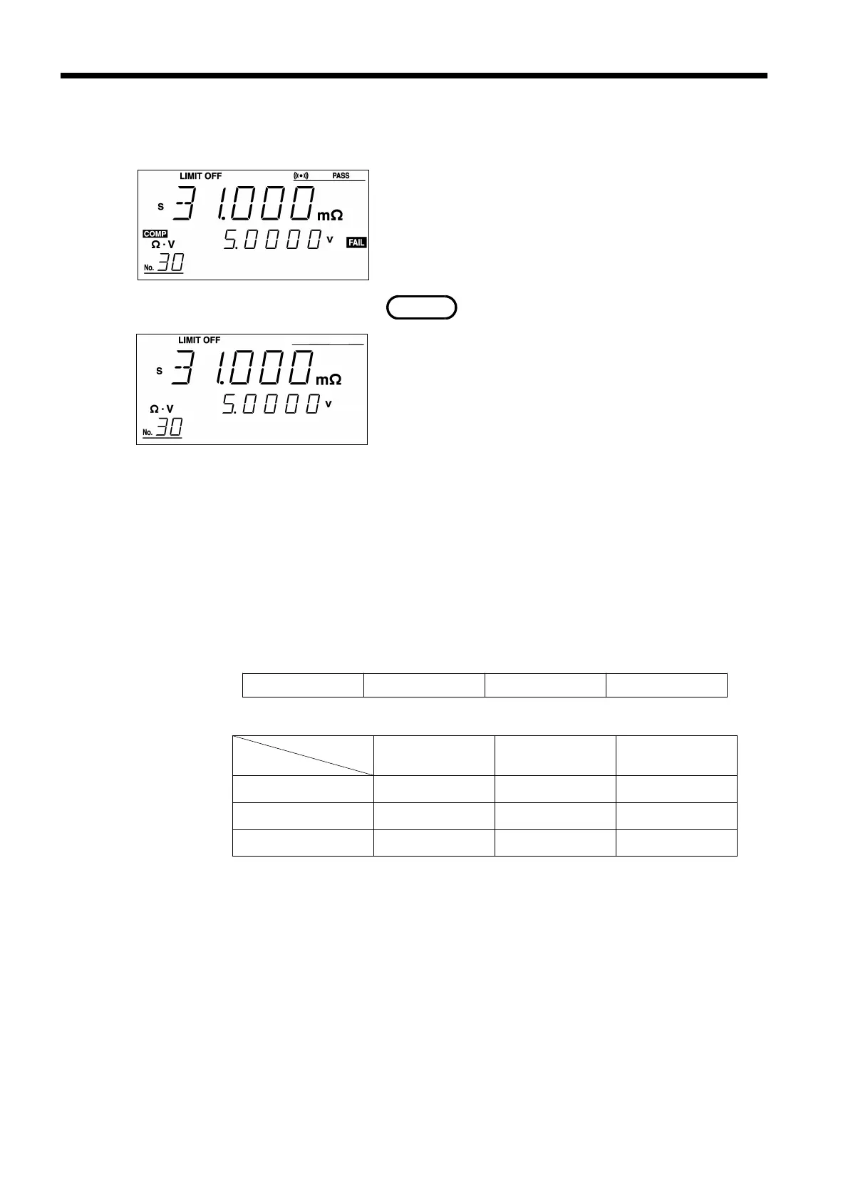
.5 Switching On/Off the Comparator
Pressing the COMP key toggles the comparator on
and off. When the comparator is on, "COMP"
appears lit on the display and the comparator
function is executed. When the comparator is off,
"COMP" is not lit, and the comparator function
does not execute.
・ If the manual comparator is selected, the
comparator function is executed while the
instrument is controlled via the EXT.I/O
terminal. For more information, see Section 5.3
"Selecting the AUTO/MANU Comparator Mode."
・ Changing the resistance or voltage range
automatically turns off the comparator. Press the
COMP key to use the comparator. This activates
the range set in the comparator.
・ In the absence of a measured value, "-----"
appears, and the comparator function is disabled.
■ Comparator comparison table
Judgment results are output to the display according to the table below.
The boundary condition is as follows:
Resistance Lo < Lower resistance limit ≦ Resistance IN
Resistance IN ≦ Upper resistance limit < Resistance Hi
Voltage Lo < Lower voltage limit ≦ Voltage IN
Voltage IN ≦ Upper voltage limit < Voltage Hi
When the upper limit is equal to the lower limit, the boundary condition
is changed as follows:
Resistance Lo ≦ Lower resistance limit = Resistance IN
Resistance IN = Upper resistance limit < Resistance Hi
Upper resistance limit < Resistance Hi
Voltage Lo ≦ Lower voltage limit = Voltage IN
Voltage IN = Upper voltage limit < Voltage Hi