28
────────────────────────────────────────────────────
4.5 Starting Measurement
────────────────────────────────────────────────────
DANGE
・ Be sure to ensure the floating state for a battery circuit (measured
object) with voltage exceeding 30 Vrms, 42.4 Vpeak, or 60 VDC.
Connecting the instrument to a circuit exceeding 30 Vrms, 42.4
Vpeak, or 60 VDC may lead to electric shock.
・ To avoid electrical shock, be careful to avoid shorting live lines
with the measurement leads.
・ Do not measure the voltage of the voltage generator, as doing so
will cause an AC voltage to be applied to the output terminal of the
voltage generator, resulting in a hazard.
・ When a high-voltage battery has been measured and a low-voltage
battery is to be measured, short-circuit the measurement lead to
discharge the DC component cutoff capacitor of the 3560.
Otherwise, an overvoltage will be applied to the battery.
946
945
9287-1
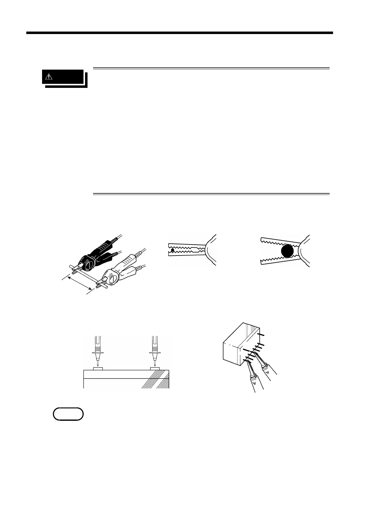
Measurement of resistance
Measurement of battery internal resistanc
Measurement of relay contact resistanc
R
When clipping a thin line
Clip the line at the tip,
serrated part of the jaws.
When clipping a thick line
(Clip the line at the deep,
non-serrated part of the jaws.
NOTE
.5 Starting Measurement
Connect the lead to the measured object and read the measured value.
・ The value displayed may fluctuate if equipment generating magnetic
fields is located near the 3560, such as electric motors. If fluctuations are
observed, install the instrument in a location at a distance from the
equipment.
・ Objects having inductance of 5 μH or greater may produce incorrect
measurements.
・ Do not pile the 3560 instruments for measurement.
・ Note that if the tested object is placed on the instrument or close to the
indicator, measurements may fluctuate due to generated noise.