60
────────────────────────────────────────────────────
7.2 Operating Procedure (RS-232C)
────────────────────────────────────────────────────
.2.10 Output Buffer
.2.11 Input Buffer
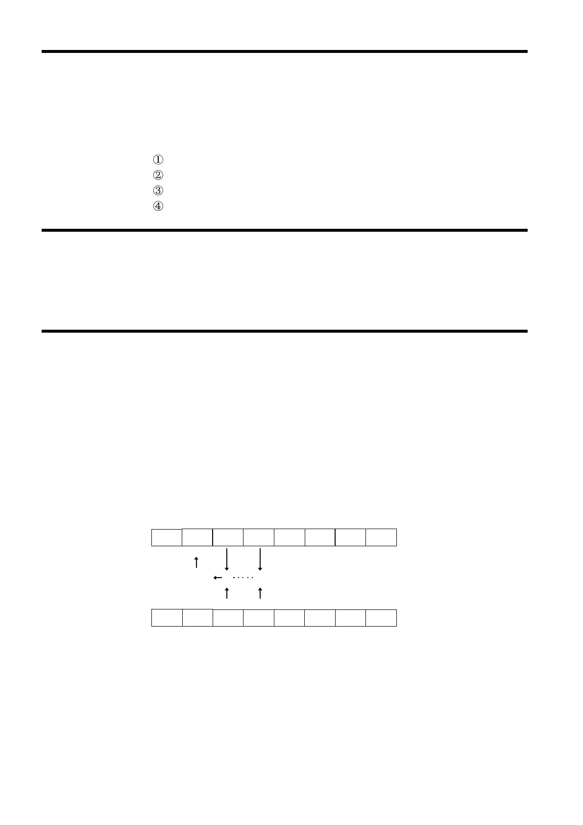
.2.12 Status Byte Registers
ESB
Not use
Not use
Not use
Not use
MSS
MAV
Logical sum
ESB MAV
Not use
×
Status byte registers(STB)
Service request enable registers
(
)
Not use
Not use
Not use
Not use
Not use
The 3560 have an output buffer of 128 bytes capacity.
Response messages accumulate in the output buffer and all data are
received and cleared.
The output buffer is also cleared in the following four situations:
When the instrument is powered on.
When the Query error is occurred.
When the Device is cleared.
When the I/F is Switched.
The 3560 have an input buffer of 128 bytes capacity.
Switching the interface clears the current setting.
(1) Status byte register (STB)
The status byte register is an 8-bit register whose contents are output
from the 3560 to the controller, when serial polling is being performed.
If even only one bit in the status byte register has changed from 0 to 1
(provided that it is a bit which has been set in the service request enable
register as a bit which can be used), then the MSS bit is set to 1.
Simultaneously with this the SRQ bit is set to 1, and service request is
generated.