61
────────────────────────────────────────────────────
7.2 Operating Procedure (RS-232C)
────────────────────────────────────────────────────
Bit Meaning
7
Not used
6
MSS
MSS shows the logical sum of other bits in the status byte
register.
5
ESB
Standard event summary (logical sum) bit
ESB shows the logical sum of the standard event status
register.
4
MAV
Message available
MAV indicates the output queue has messages.
3
Not used
2
Not used
1
Not used
.2.13 Event Registers
DDE
URQ
CME EXE
Logical sum
CME EXE
PON URQ
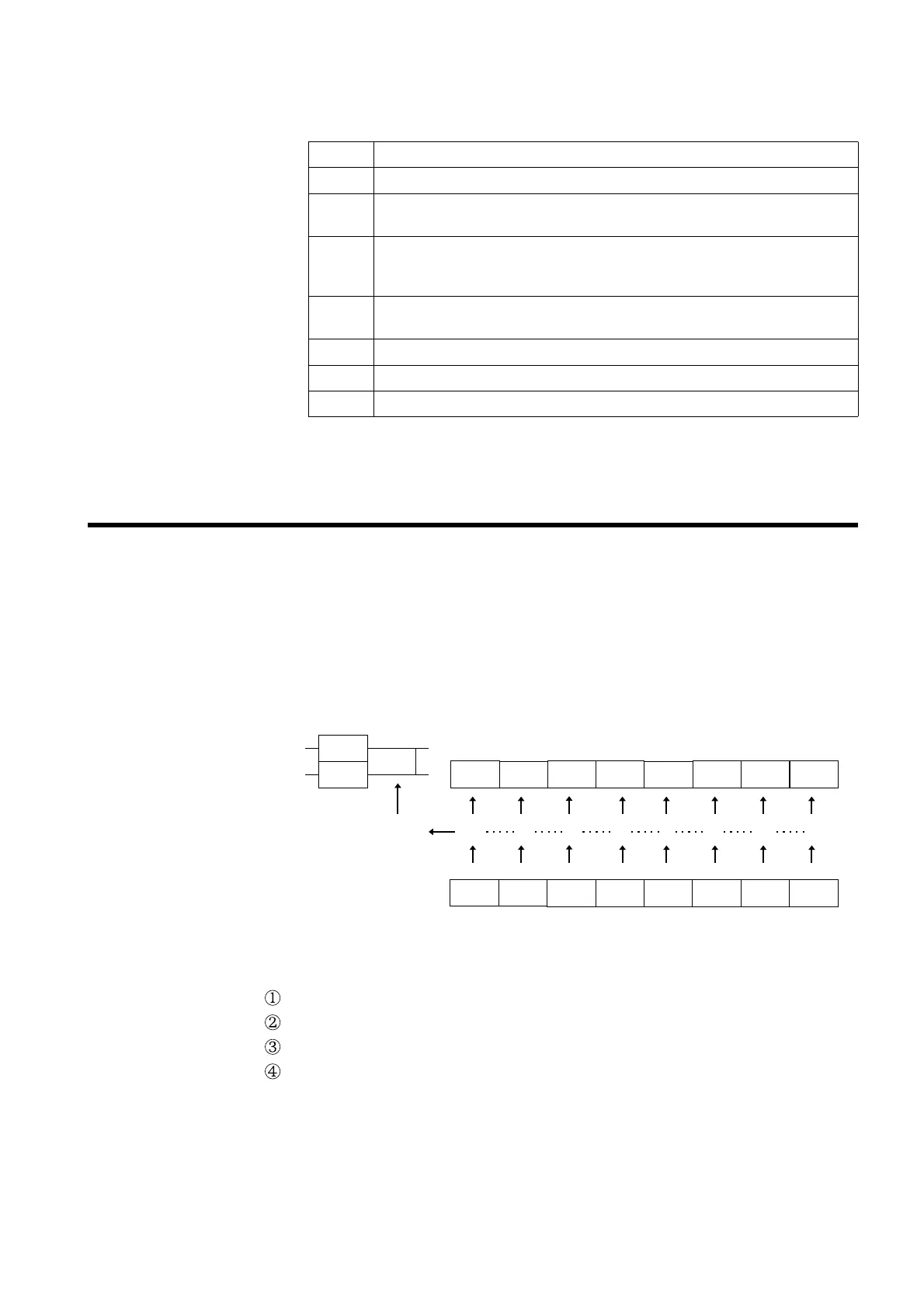
Status byte registers(STB)
Service request enable register
(SRER)
DDE QYE RQC OPC
QYE RQC OPCPON
ESB
RQS
MSS
Although the MSS bit is read out on an *STB? query, on a *CLS command
for example it is not cleared until the event is cleared.
(2) Service request enable register (SRER)
This register masks the status byte register. Setting a bit of this register
to 1 enables the corresponding bit of the status byte register to be used.
(1) Standard event status register (SESR)
The standard event status register is an 8-bit register. If any bit in the
standard event status register is set to 1 (after masking by the standard
event status enable register), bit 5 (ESB) of the status byte register is set
to 1.
The standard event status register is cleared in the following four
situations:
When a *CLS command is received.
When an *ESR? query is received.
When the instrument is powered on.
When the I/F is Switched.