11
────────────────────────────────────────────────────
3.1 Mounting the Interface
────────────────────────────────────────────────────
1
2
3
4
5
6
7
8
9
10
11
12
13
14
A
WARNIN
To avoid electric shock accident, before removing or replacing an
interface, confirm that the instrument is turned off and that the
power cord is disconnected. The mounting screws must be firmly
tightened or the interface may not perform to specifications, or
may even fail.
To avoid the danger of electric shock, never operate the instrumen
with an interface removed. To use the instrument after removing an
interface, install a blank panel over the opening of the removed
module.
CAUTIO
To avoid damage to the instrument, do not short-circuit the output terminal
or connector and do not input voltage to the output terminal or connector.
When the interface is removed, place a blank panel over the opening. This
keeps the instrument’s internal temperature uniform and within
specifications.
NOTE
Chapter
Preparing for Measureme
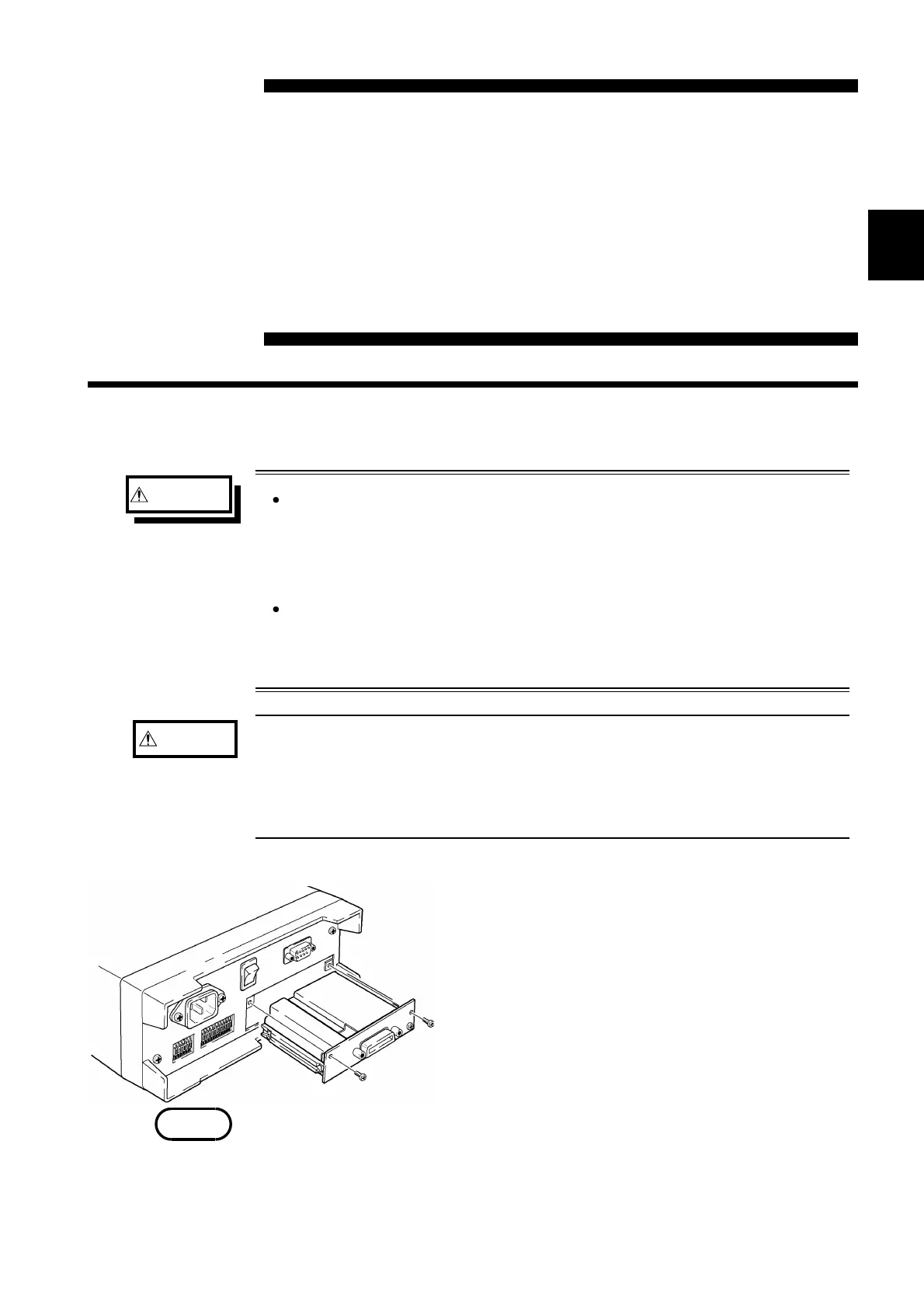
.1 Mounting the Interface
The 9588 GP-IB INTERFACE or 9589 PRINTER INTERFACE can be
mounted to the instrument.
An expansion slot for an interface is covered by a
blank panel on the rear panel of the instrument.
To mount an interface, remove this panel in the
following manner:
1. Remove the blank panel. (Retain the set bolts.)
2. Insert the interface into the guide rails.
3. Firmly press the interface into the slot until
fully inserted, and secure with the set bolts from
Step 1.
・ Mount only a 9588 or 9589 interface.
・ The resistance or voltage can be measured even if the interfaces is not
mounted.
・ The printer and GP-IB interfaces cannot be used simultaneously. Mount
either interface.