3
────────────────────────────────────────────────────
1.3 Identification of Controls and Indicators
────────────────────────────────────────────────────
1
2
3
4
5
6
7
8
9
10
11
12
13
14
A
1
2
3
4
5
6
7
8
9
10
11
12
13
14
A
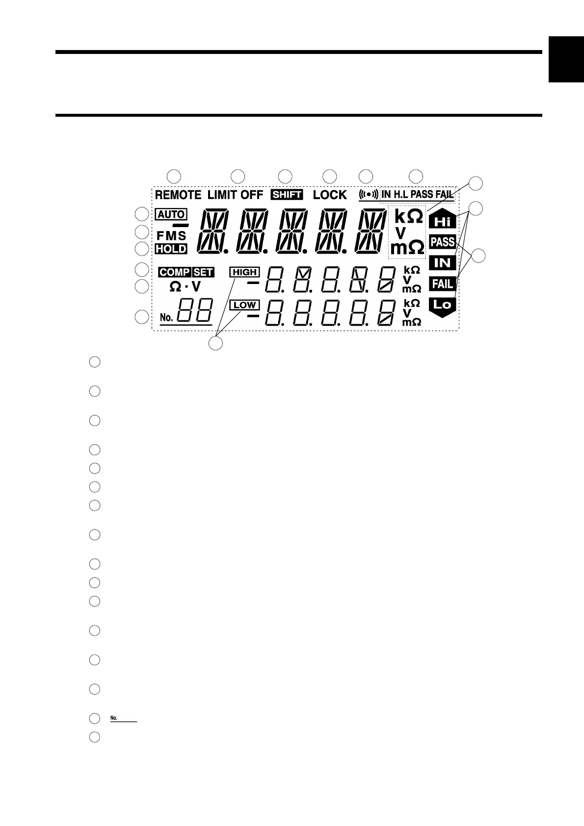
.3.1 Fluorescent Character Display Tube
REMOTE This indicator lights to indicate control through RS-232C or GP-IB
interfaces.
LIMIT OFF This indicator lights to indicate that open-circuit terminal voltage is
not limited to 20 mV.
SHIFT This symbol appears when this key is pressed, and disappears when
any other key is pressed.
LOCK This indicator lights to indicate that the key lock is active.
Buzzer (1) This symbol indicates that the buzzer is enabled.
Buzzer (2) This indicator displays the buzzer setting for the selected comparator.
AUTO This symbol appears to indicate that the resistance or voltage range is
set to auto-range.
FMS This indicator displays the sampling rate setting. "F" stands for Fast;
"M" stands for Medium; and "S" stands for Slow.
HOLD This indicator lights to indicate that the instrument is in hold mode.
kΩ/V/mΩ These symbols indicate various instruments.
Hi/IN/Lo This symbol indicates comparator operation results in resistance
measurement mode.
PASS/FAIL This symbol displays comparator operation results in resistance and
voltage measurement mode.
COMP SET This symbol lights to indicate use of either the comparator function
("COMP" is lit) or set ("COMP SET" is lit).
Ω・V This symbol indicates either resistance mode ("Ω" is lit) or resistance
and voltage mode ("Ω" is lit)
This symbol indicates the comparator number.
HIGH/LOW This symbol indicates the upper and lower limits of the comparator.
.3 Identification of Controls and Indicators