54
────────────────────────────────────────────────────
7.1 Connection to Computer (RS-232C)
────────────────────────────────────────────────────
WARNIN
To avoid electrocution, turn off the power to all devices before
plugging or unplugging any of the interface connectors.
To avoid damage to the instrument, do not short the output terminal
and do not input voltage to the output terminal.
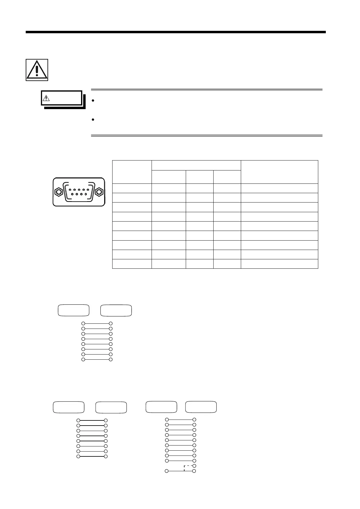
Rear panel of the instrument
Connecto
(D-sub)
Pin numbe
Signal
Name
RS-232C CCITT JIS
1 Not used
2 BB(RxD) 104 RD Data of reception
3 BA(TxD) 103 SD Data of transmission
4 CD(DTR) 108/2 ER Data terminal ready
5 AB(GND
102 SG Signal ground
6 CC(DSR) 107 DR Not used
7 CA(RTS) 105 RS Request for transmission
8 CB(CTS) 106 CS Transmission ready
9 Not used
Cabl
Conversion connecto
Cabl
.1 Connection to Computer (RS-232C)
To connect the 3560 and a PC, attach one end of the RS-232C cable to the
instrument’s RS-232C connector and the other end to the PC serial port.
■ Usable cable conditions
Connection: Reverse-type connection
The figure below gives a wiring diagram.
This particular example shows a connection to a PC/AT
compatible.
■ Connecting to PC98 compatibles
Use a 9-pin cable and 9/25
conversion pin connector to
connect the 3560 to a PC98-
series machine.