31
────────────────────────────────────────────────────
────────────────────────────────────────────────────
1
2
3
4
5
6
7
8
9
10
11
12
13
14
A
The on/off status for the buzzer can be changed in the
comparator setting.
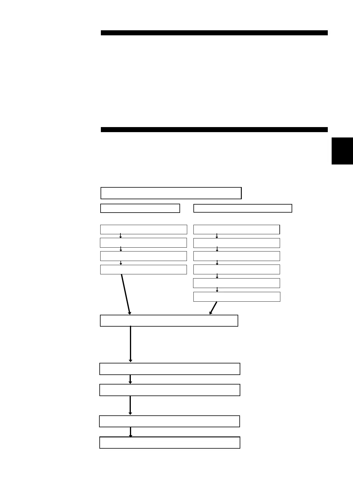
Setting the buzzer mode
Switching on/off the comparator
Setting the comparator functions
Setting the comparator numbe
Setting the resistance range
Setting the resistance value
Setting the voltage range
Setting the voltage value
Setting the buzzer mode
See Section 5.2
Setting the comparator numbe
Setting the resistance range
See Section 5.1
See Section 5.
See Section 5.
See Section 5.
See Section 5.
Resistance measurement mod
This instrument supports two mode options: an auto
comparator mode in which the comparator is used for every
sampling to display and output results, and a manual
comparator mode in which comparator operation results are
output only when the result indication is requested.
Resistance and voltage measurement mode
Changing the comparator number
Setting the resistance value
Selecting the AUTO/MANU comparator mod
Use the View function to check the upper and lower limits of
the currently set comparator.
Changing the on/off status for the buzzer
See Section 4.3.
Checking the comparator conditions (view)
Chapter
Comparator Functio
With the comparator function, the instrument compares the measured
value to the predetermined upper and lower limits to determine, based on
set conditions, where the measured value falls in this range, then
displays and outputs the result. The following flowchart illustrates the
setup sequence.