42
────────────────────────────────────────────────────
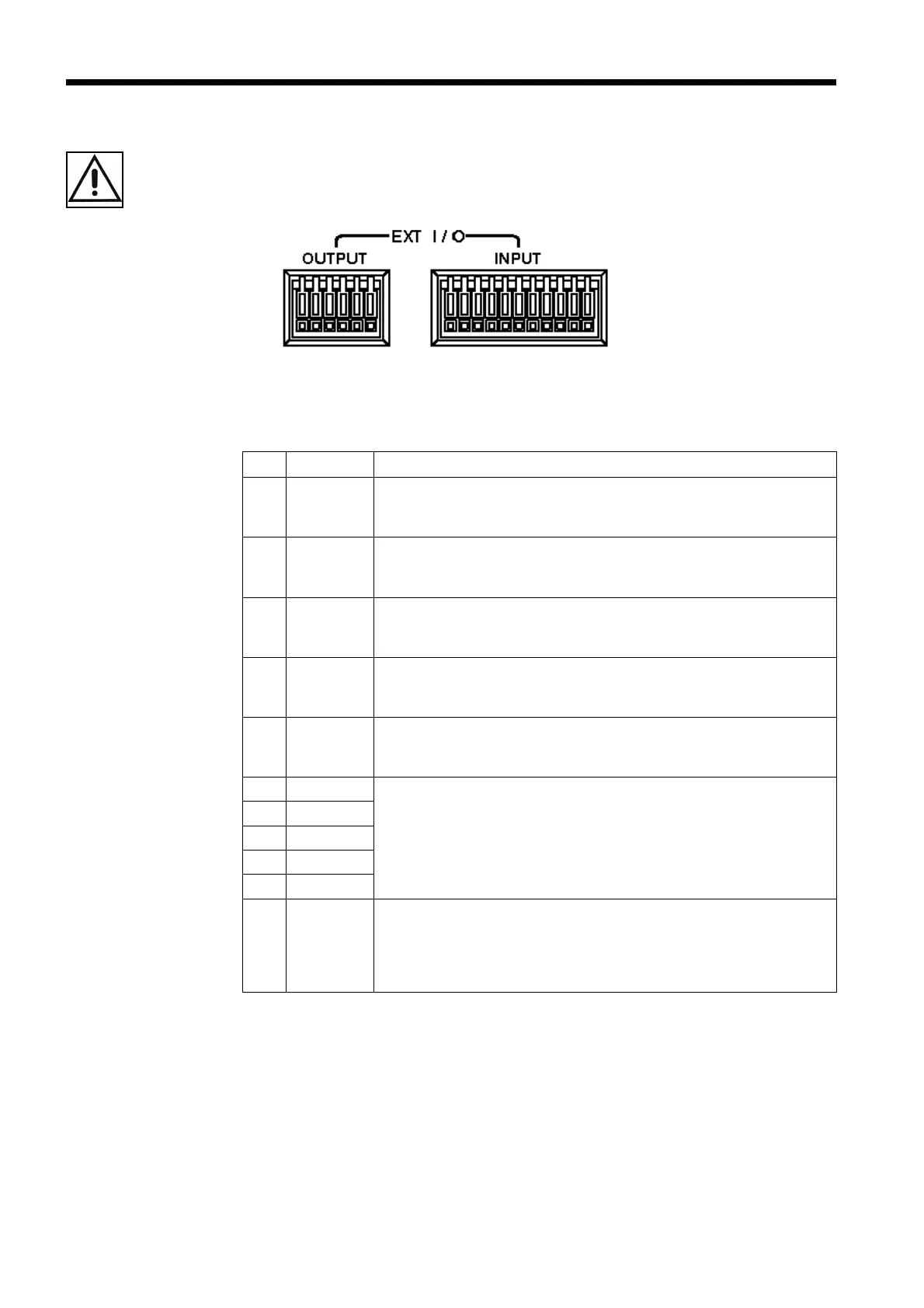
6.1 Terminals and Signals
────────────────────────────────────────────────────
No
Termina
Meaning
7 GND
Digital ground
This terminal is connected to GND of the external
output terminal inside the instrument.
8 TRIG
Measurement trigger terminal
This terminal is enabled when the instrument is in
hold mode. See the timing chart.
9 MANU
Comparator trigger terminal
This terminal is enabled in manual comparator mode.
See the timing chart and comparator setting.
10 0ADJ
Zero-adjust control terminal
This terminal provides the same function provided by
the
0ADJ key.
11 PRINT
Print trigger terminal
This terminal is connected to the optional 9203
DIGITAL PRINTER.
12 COMP.0
Comparator selection terminal
Comparator conditions are loaded according to the
comparator selection table. You may select a
comparator from 1 to 30.
13 COMP.1
14 COMP.2
15 COMP.3
16 COMP.4
17 EXT.DCV
Terminal used to provide power-supply voltage to the
instrument from external equipment Allowable power-
supply voltages range from +5 to +30 VDC. The
external equipment is connected to this terminal via an
open-collector output transistor emitter and resistor.
.1 Terminals and Signals
■ External control terminals